Wind tunnel test model assembly and disassembly assistance system

A wind tunnel test and auxiliary system technology, applied in the field of aerodynamics, can solve the problems of reducing the assembly accuracy of each part of the model, damage to the surface of the model and screw holes, difficulty in assembly and disassembly of the model, etc., to achieve automatic operation and simple appearance. , the effect of convenient installation

Inactive Publication Date: 2017-05-10
LOW SPEED AERODYNAMIC INST OF CHINESE AERODYNAMIC RES & DEV CENT
View PDF8 Cites 1 Cited by
  • Summary
  • Abstract
  • Description
  • Claims
  • Application Information

AI Technical Summary

Problems solved by technology

This structural form makes the assembly and disassembly of the model more difficult, such as figure 1 Shown: In order to install the first model part (considered as the movable part) to the lip section on the second model part (considered as the fixed part), it is usually necessary to tap the first model part with a tool such as a rubber hammer to make it along the The seam section moves forward and approaches the second model part, and finally makes the end surfaces of the two parts contact, and then fastens them with pins and screws; similarly, in order to disassemble the first model part from the second model part, the two parts are separated , you have to insert the screw into the screw hole of the movable part, use a hammer to hit the screw, and the screw drives the first model part to move out of the stop section of the second model part in the opposite direction
This assembly and disassembly method is not only time-consuming and labor-intensive, but also highly dependent on the practical experience of the operator; in addition, it will cause certain damage to the model surface and screw holes, and reduce the assembly accuracy between the various parts of the model

Method used


Image

  • Wind tunnel test model assembly and disassembly assistance system
  • Wind tunnel test model assembly and disassembly assistance system

Examples


Embodiment Construction

[0034] The following will clearly and completely describe the technical solutions in the embodiments of the present invention with reference to the drawings in the embodiments of the present invention.

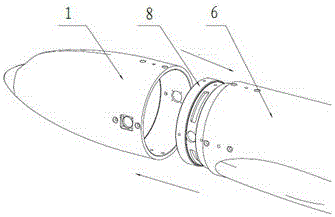
[0035] Such as figure 1 As shown, the test model consists of two parts, one is the fixed model part, the other is the movable model part, the connection part on the fixed model part is the mouth section, in order to ensure the integrity of the test model when doing the test, the movable model needs to be The component is fixedly connected with the fixed model component. However, the traditional method is like the operation described in the background art, but it will bring various adverse consequences, resulting in a decrease in test accuracy.

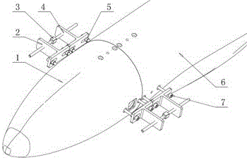
[0036] Such as figure 2 As shown, in order to solve the problem, this scheme provides a set of auxiliary tools for fast and easy connection of fixed model parts and movable model parts. Fixing holes are respectively arranged on the...


PUM


Abstract

The invention discloses a wind tunnel test model assembly and disassembly assistance system comprising a movable model part and a second connecting substrate mounted thereon, a fixed model part and a first connecting substrate mounted thereon. A screw is arranged between the two connecting substrates. The thread directions at the joints of the screw and the two substrates are different so that the rotation of the screw drives the two connecting substrates to move to each other. According to the invention, the thread directions at both ends of the screw are different from each other and the thread directions of the two substrates are also different from each other so that the two substrates can be moved in the same direction or in the opposite direction when the screws are rotated in different directions. The various parts of the wind tunnel test model assembly and disassembly assistance system are simple in appearance, convenient in installation and simple in operation. An actual operation shows that the assembly and disassembly of the wind tunnel test model becomes time-saving and labor-saving and does not cause any damage to the model.

Description

technical field [0001] The invention relates to the field of aerodynamics, in particular to a system for installing and dismounting various parts of a wind tunnel test model. Background technique [0002] The wind tunnel test model is generally composed of parts such as the nose, the middle fuselage, and the rear fuselage. In order to ensure the reliability of the connection of each part, the model designer will design a certain length of the joint at the connection part, and use a gap between the two parts. Small tight fit. This structural form makes the assembly and disassembly of the model more difficult, such as figure 1 Shown: In order to install the first model part (considered as the movable part) to the lip section on the second model part (considered as the fixed part), it is usually necessary to tap the first model part with a tool such as a rubber hammer to make it along the The seam section moves forward and approaches the second model part, and finally makes t...

Claims


Application Information

Patent Timeline
Patent Type & Authority Applications(China)
IPC IPC(8): G01M9/08
CPCG01M9/08
Inventor 李东孙传宝周晓飞孔鹏江鲲鹏张俊伟靳清岭
Owner LOW SPEED AERODYNAMIC INST OF CHINESE AERODYNAMIC RES & DEV CENT
Why Eureka
Try Eureka