Chirality coupling core diameter optical fiber and manufacturing method thereof

A manufacturing method and chiral technology, applied in the field of chiral coupled core fiber and its manufacturing, can solve the problems of difficult, inconvenient and difficult manufacturing of optical fiber, and achieve low difficulty in position control and low manufacturing cost , the effect of low manufacturing difficulty

Active Publication Date: 2013-07-17
FENGHUO COMM SCI & TECH CO LTD
View PDF4 Cites 7 Cited by
  • Summary
  • Abstract
  • Description
  • Claims
  • Application Information

AI Technical Summary

Problems solved by technology

[0008] (1) When a mechanical drill drills a circular through hole, due to the need to ensure the roughness of the inner surface of the processed through hole and the matching degree between the processed through hole and the satellite core preform, the mechanical drill requires a higher The mechanical processing accuracy; and the mechanical drill drills the through hole, and the strength of the drill bit of the mechanical drill is difficult to control. With the increase of the depth of the processed through hole, the tip of the drill bit of the mechanical drill will produce a swing in the direction of the outer wall of the guiding fiber core preform. Dynamic centrifugal force, which in turn causes the size of the two ends of the processed through hole to be different
Therefore, it is difficult to manufacture

Method used


Image

  • Chirality coupling core diameter optical fiber and manufacturing method thereof
  • Chirality coupling core diameter optical fiber and manufacturing method thereof
  • Chirality coupling core diameter optical fiber and manufacturing method thereof

Examples


Embodiment 1

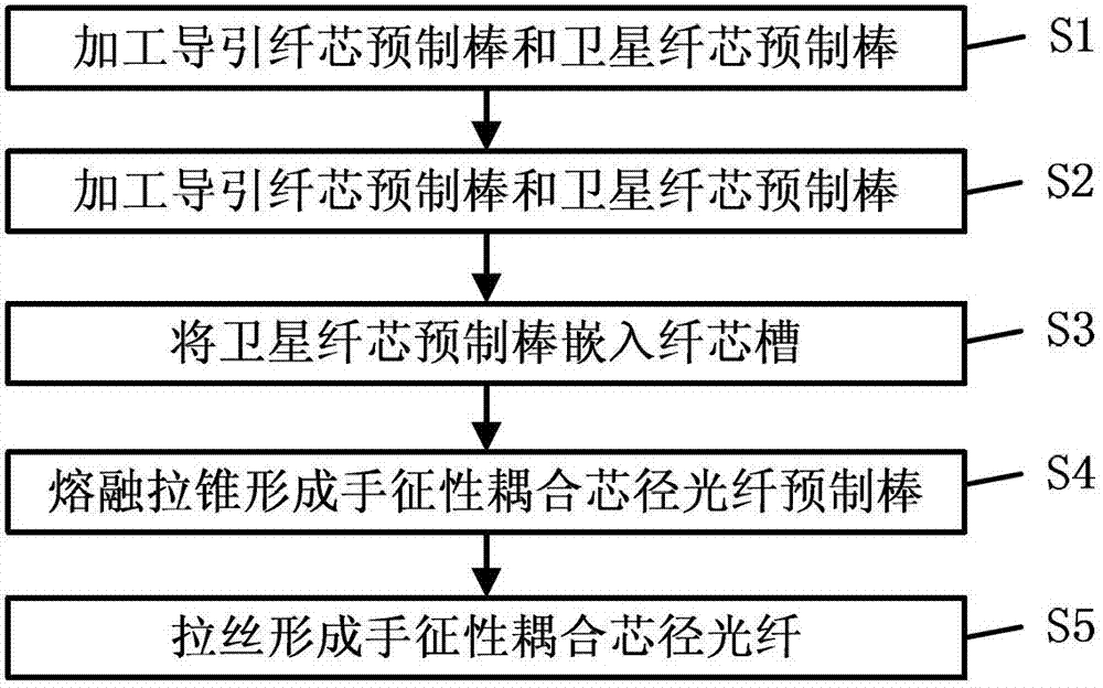
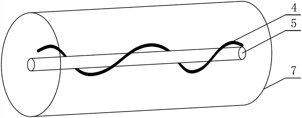
[0045] Embodiment 1: Manufacture a chiral coupled core fiber 7 with a beam quality of 1.07.

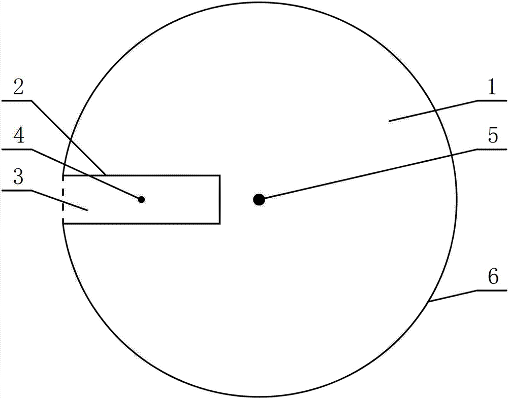
[0046] Select cladding diameter as 42.10mm, the diameter of guiding fiber core 5 is 7.50mm guiding fiber core prefabricated rod semi-finished product, on the outer wall of guiding fiber core prefabricated rod semi-finished product along the radial direction open fiber core groove 2, form the The core trench 2 guides the core preform rod 1 . The cross-section of the core slot 2 is rectangular. According to the shape of the core slot 2, the satellite core preform semi-finished product (the satellite core 4 rare earth doping inside the satellite core preform semi-finished product) is processed to form a satellite core preform 3. The cross-section of the satellite core preform 3 is also rectangular, with a length of 17.05 mm and a width of 9.60 mm; the size deviation between the satellite core preform 3 and the fiber core slot 2 is 0.15 mm.

[0047] Polish the core slot 2, insert the sa...

Embodiment 2

[0050] Embodiment 2: Manufacturing a chiral coupled core fiber 7 with a beam quality of 1.09.

[0051] Select cladding diameter as 12.12mm, the diameter of guiding core 5 is 3.60mm guiding fiber core prefabricated rod semi-finished product, on the outside wall of guiding fiber core prefabricated rod semi-finished product radially open fiber core groove 2, form the The core trench 2 guides the core preform rod 1 . The cross-section of the core slot 2 is rectangular. According to the shape of the core slot 2, the satellite core preform semi-finished product (the satellite core 4 rare earth doping inside the satellite core preform semi-finished product) is processed to form a satellite core preform 3. The cross-section of the satellite core preform 3 is also rectangular, with a length of 4.22 mm and a width of 2.17 mm; the size deviation between the satellite core preform 3 and the fiber core slot 2 is 0.11 mm.

[0052] Polish the core slot 2, insert the satellite core preform ...

Embodiment 3

[0055] Embodiment 3: Manufacturing a chiral coupled core fiber 7 with a beam quality of 1.01.

[0056] Select the guide fiber core prefabricated semi-finished product whose cladding diameter is 72.01mm and the diameter of the guide fiber core 5 is 16.40mm, open the fiber core groove 2 radially on the outer wall of the guide fiber core preform semi-finished product to form a The core trench 2 guides the core preform rod 1 . The cross-section of the core slot 2 is rectangular. According to the shape of the core slot 2, the satellite core preform semi-finished product (the satellite core 4 rare earth doping inside the satellite core preform semi-finished product) is processed to form a satellite core preform 3. The cross-section of the satellite core preform 3 is also rectangular, with a length of 32.92 mm and a width of 17.87 mm; the size deviation between the satellite core preform 3 and the core slot 2 is 0.23 mm.

[0057] Polish the core slot 2, insert the satellite core pr...


PUM

PropertyMeasurementUnit
Diameteraaaaaaaaaa
Diameteraaaaaaaaaa
Diameteraaaaaaaaaa

Abstract

The invention discloses a chirality coupling core diameter optical fiber and a manufacturing method thereof and relates to the field of optical fiber laser transmission and amplification. The manufacturing method comprises the following steps of: processing a guide fiber core preform semifinished product and a satellite fiber core preform semifinished product to form a satellite fiber core preform and a guide fiber core preform; embedding the satellite fiber core preform into a fiber core slot; carrying out fused biconical taper at the top of the guide fiber core preform to form a chirality coupling core diameter optical fiber preform; and carrying out melting and wire drawing on the chirality coupling core diameter optical fiber preform to form a chirality coupling core diameter optical fiber. Output optical beam quality of the chirality coupling core diameter optical fiber is less than 1.1, fundamental mode loss is less than 0.5dB/m, and high-order mode loss is more than 100dB/m. The chirality coupling core diameter optical fiber manufactured by the invention is good in optical property and reliability, low in manufacturing difficulty and applicable to mass production.

Description

technical field [0001] The invention relates to the field of optical fiber laser transmission and amplification, in particular to a chiral coupling core-diameter optical fiber and a manufacturing method thereof. Background technique [0002] Fiber laser is a laser that uses optical fiber as the fiber medium. Fiber laser has become one of the mainstream lasers in the field of laser applications due to its high conversion efficiency, good heat dissipation performance and stability. [0003] With the continuous expansion of laser application fields, users have higher and higher demands on the output power of fiber lasers. People generally use large-mode-field-area fibers to increase the output power of fiber lasers; since the laser mode oscillation in the large-mode-field fiber core will cause beam quality degradation, in order to optimize the beam quality, people generally reduce the numerical aperture of the fiber core The way. However, the decrease in the numerical apertur...

Claims


Application Information

Patent Timeline
IPC IPC(8): C03B37/012C03B37/027
CPCC03B2203/20C03B37/01205C03B2203/32C03B37/01234C03B37/02745C03B2203/34G02B6/02042G02B2006/0209
Inventor 杜城陈伟李诗愈莫琦张涛柯一礼罗文勇杜琨胡福明
Owner FENGHUO COMM SCI & TECH CO LTD
Why Eureka
Try Eureka