Illumination device and method of making the device

a technology of led-based illumination and a mounting device, which is applied in the direction of coupling device connection, lighting and heating apparatus, lighting heating/cooling arrangements, etc., can solve the problem of non-uniform intensity of light from such an led-based illumination devi

Inactive Publication Date: 2010-06-15
AVAGO TECH INT SALES PTE LTD
View PDF26 Cites 58 Cited by
  • Summary
  • Abstract
  • Description
  • Claims
  • Application Information

AI Technical Summary

Problems solved by technology

However, these LED-based illumination devices can at best produce a hemispheric illumination.
Furthermore, the intensity of light from such an LED-based illumination device tends to be non-uniform.

Method used


Image

  • Illumination device and method of making the device
  • Illumination device and method of making the device
  • Illumination device and method of making the device

Examples


Embodiment Construction

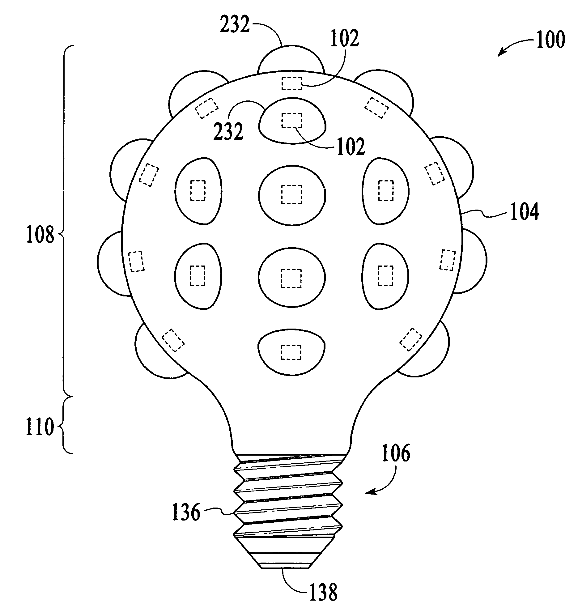
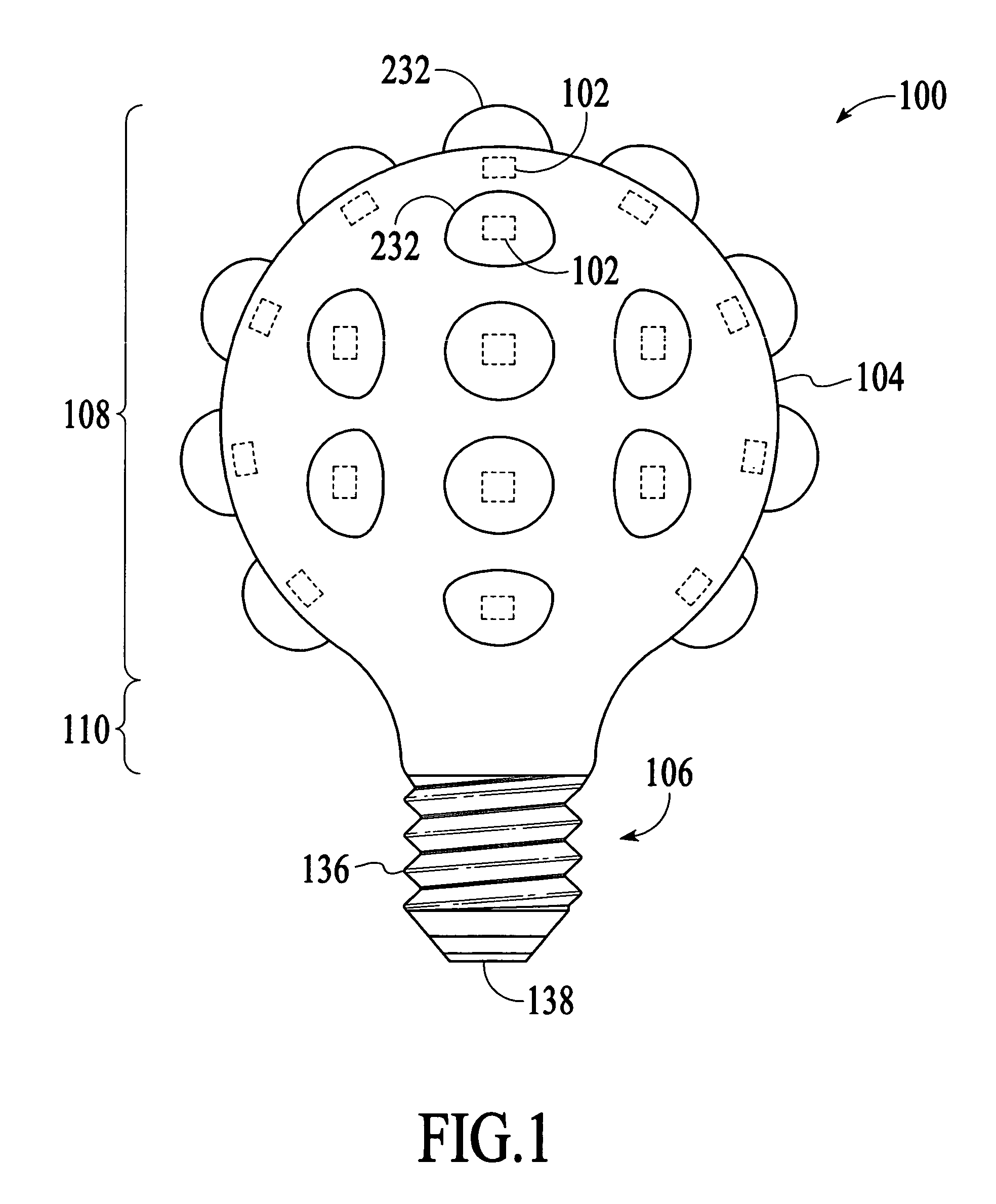
[0015]With reference to FIG. 1, an illumination device 100 in accordance with an embodiment of the invention is described. The illumination device 100 includes a number of light-emitting dies 102, which may be light-emitting diode (LED) dies or laser diodes, to emit light in multiple directions to produce a multi-directional illumination similar to that of conventional incandescent light bulbs. In the embodiment illustrated in FIG. 1, the illumination device 100 is configured to produce a substantially spherical illumination, which provides light in virtually all directions from the illumination device.

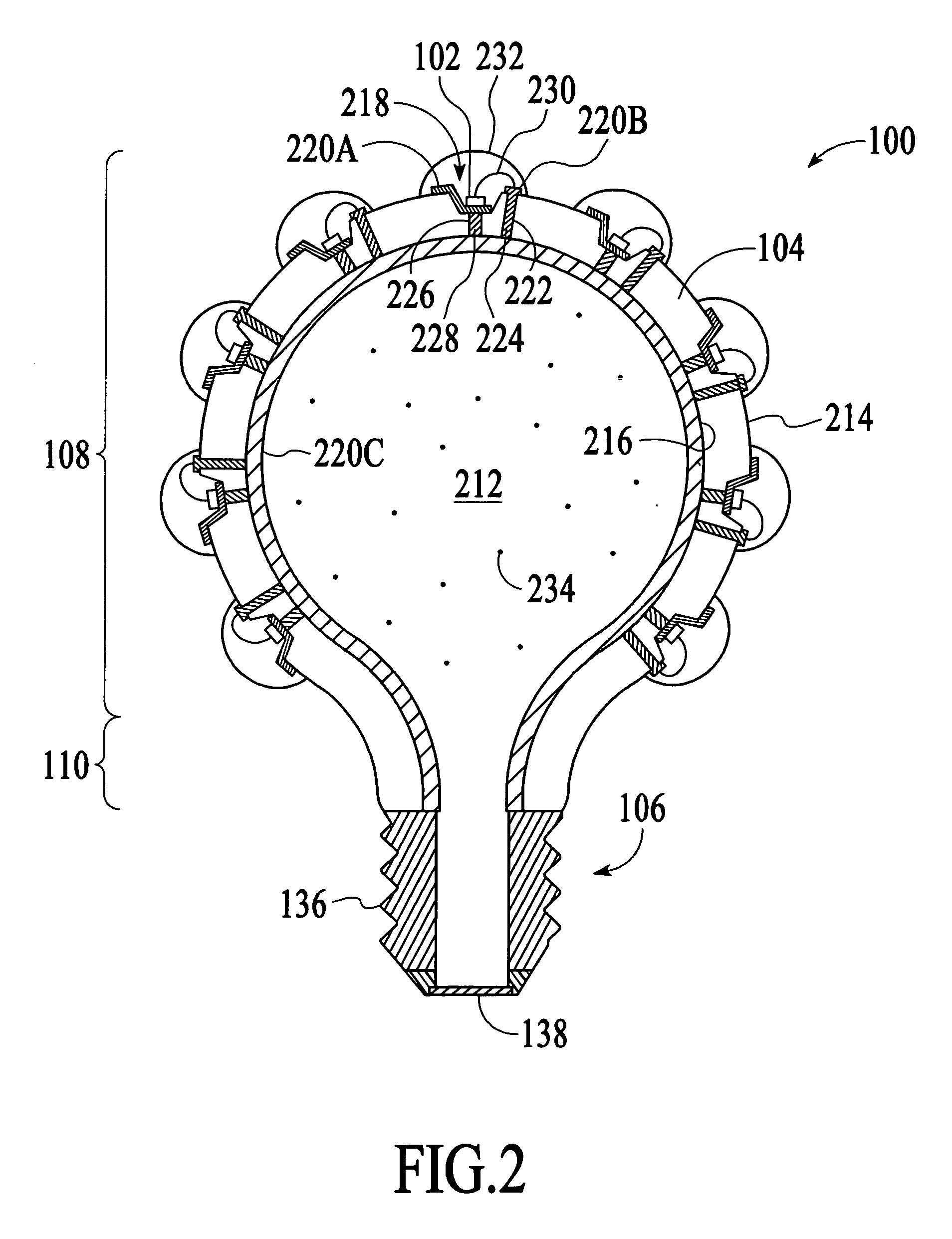
[0016]As shown in FIG. 1, the illumination device 100 includes a three-dimensional (3D) substrate 104, the light-emitting dies 102 and a screw cap 106. The 3D substrate 104 is the main structure of the illumination device 100. The 3D substrate 104 is a bulb-shaped structure. In the embodiment illustrated in FIG. 1, the 3D substrate 104 has a shape similar to the glass envelope of a ty...


PUM


Abstract

An illumination device and method of making the device uses a three-dimensional (3D) substrate on which a number of light-emitting dies are mounted. The 3D substrate is configured to define an interior region. The illumination device includes electrical traces on at least one of the exterior surface and the interior surface of the 3D substrate.

Description

BACKGROUND OF THE INVENTION[0001]Light emitting diodes (“LEDs”) have many advantages over conventional light sources, such as incandescent, halogen and fluorescent lamps. These advantages include longer operating life, lower power consumption and smaller size. Consequently, conventional light sources are increasingly being replaced with LEDs in traditional lighting applications. As an example, LEDs are currently being used in light bulbs, flashlights, traffic signal lights, automotive exterior and interior lights and display devices.[0002]A typical LED includes an LED die mounted on a substrate, such as a leadframe, and encapsulated in a molded transparent lamp package. Since the light output of an LED is limited, the LED die may be mounted in a reflector cup formed on the substrate to collect the light emitted by the LED die and direct the light upward toward the top of the transparent lamp package. Moreover, the transparent lamp package of the LED may have a domed top, which funct...

Claims


Application Information

Patent Timeline
Patent Type & Authority Patents(United States)
IPC IPC(8): F21S4/00
CPCF21K9/135F21Y2101/02F21V29/56H05K1/0284F21Y2111/004F21K9/232F21Y2115/10F21Y2107/20
Inventor BAROKY, TAJUL AROSHCHUA, JANET BEE YIN
Owner AVAGO TECH INT SALES PTE LTD
Why Eureka
Try Eureka