Releasable connection mechanism for variable stride exercise devices

a technology of adjustable connection mechanism and exercise device, which is applied in the field of adjustable connection mechanism used with stationary striding exercise device, to achieve the effect of reducing or restricting the user's ability to dynamically vary his stride path

Active Publication Date: 2010-06-15
NAUTILUS INC
View PDF122 Cites 52 Cited by
  • Summary
  • Abstract
  • Description
  • Claims
  • Application Information

AI Technical Summary

Benefits of technology

[0008]Aspects of the present invention involve an exercise device that provides a variable size foot path during use. More particularly, the exercise device includes a pair of foot platforms on which the user places his or her feet, and wherein each foot platform is operably connected with a corresponding linkage assembly. The foot platforms travel through a closed curved path of travel that varies as a function, at least in part, of the forces imparted by the user during exercise. Other aspects of the present invention involve a releasable connection mechanism for variable stride exercise devices. Embodiments of the releasable connection mechanism provide for selective and / or automated coupling of various elements of the linkage assemblies on the exercise devices so as to eliminate or limit the user's ability to dynamically vary his stride path. As such, the releasable connection mechanism can be used to allow a user to selectively configure the exercise device with a fixed stride path.
[0009]In one aspect of the present invention, an exercise device includes: a frame; at least one swing link pivotally connected with the frame; at least one crank arm pivotally connected with the frame and configured to rotate about a crank axis; at least one link movingly coupled with the at least one crank arm and operably coupled with the at least one swing link, the at least one link coupled with the at least one crank arm to allow relative movement between the at least one link and the at least one crank arm along at least a first portion of the at least one link; and at least one locking member movable to operably engage the at least one link and the crank arm to reduce relative movement between the at least one link and the at least one crank arm along at least the first portion of the at least one link.

Problems solved by technology

Thus, these exercise devices confine the range of motion of a user's foot by fixing the path traveled by the first and second ends of the foot links.

Method used


Image

  • Releasable connection mechanism for variable stride exercise devices
  • Releasable connection mechanism for variable stride exercise devices
  • Releasable connection mechanism for variable stride exercise devices

Examples


first embodiment

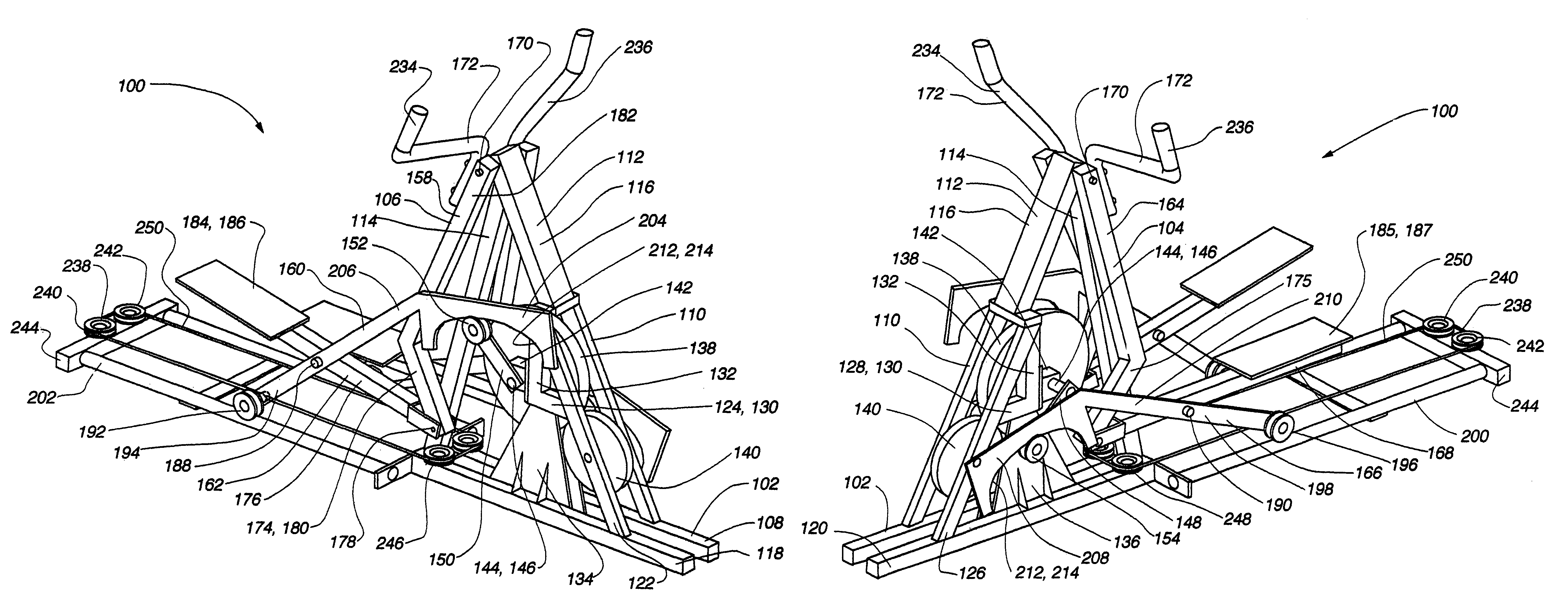
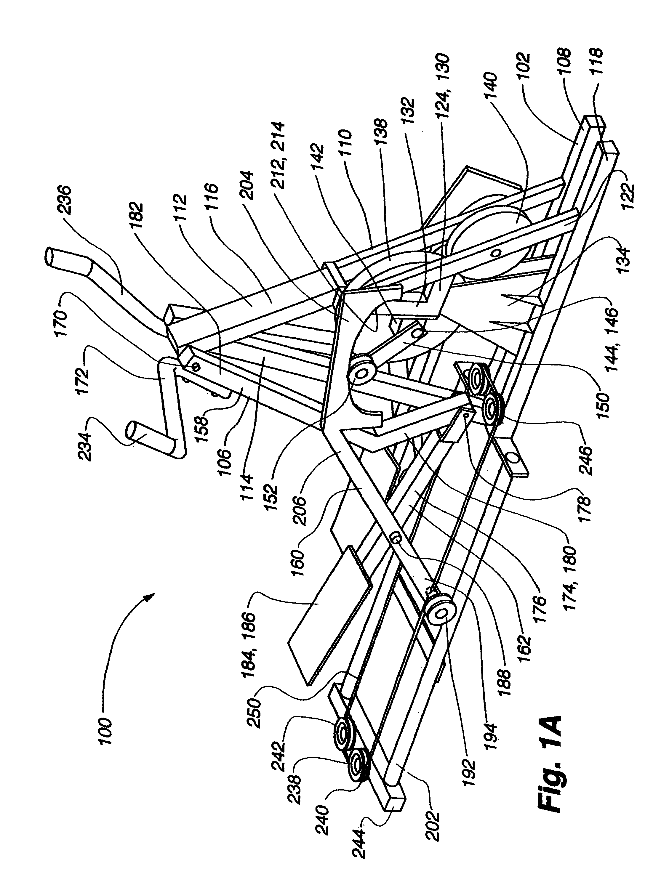
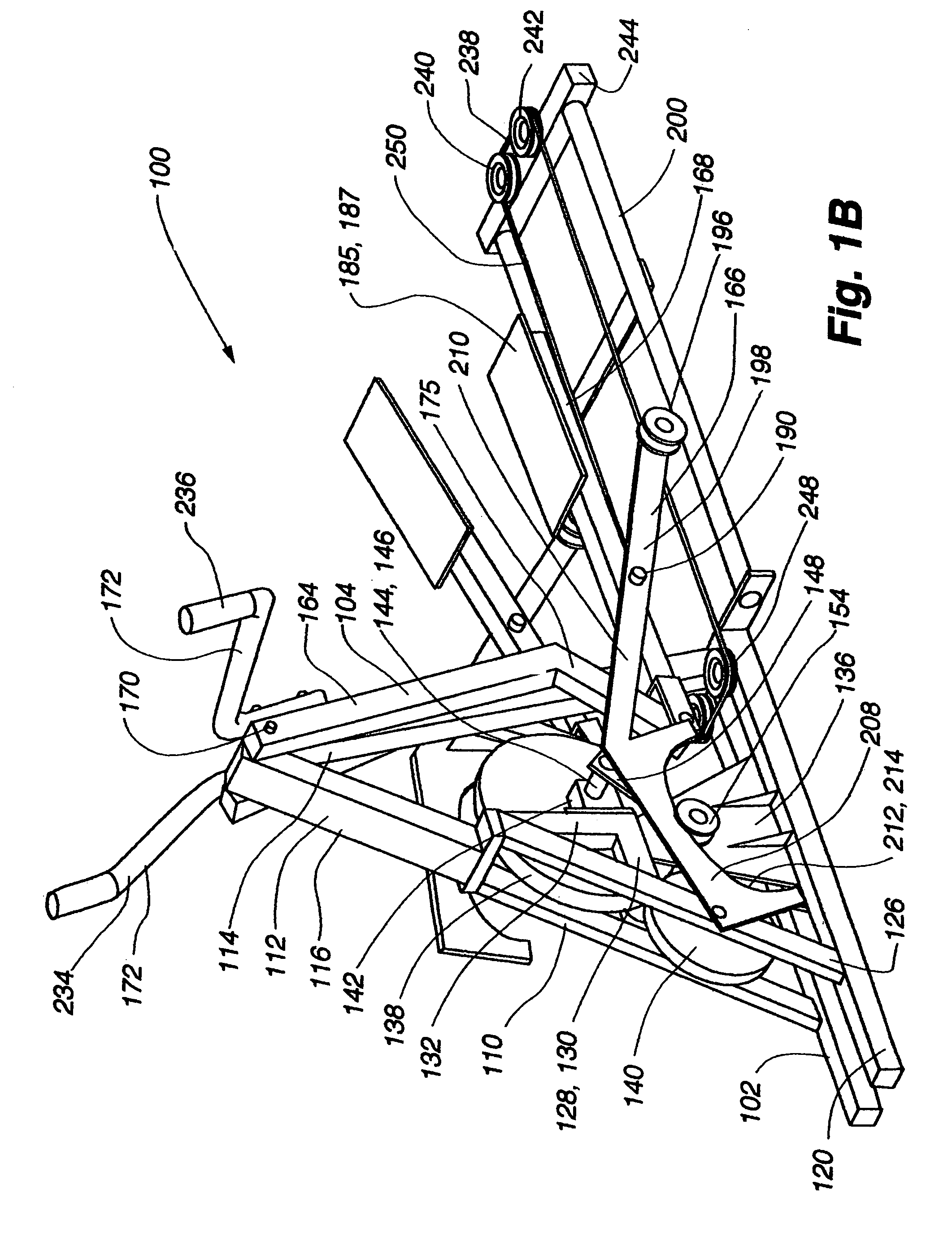
[0099]an exercise device 100 conforming to aspects of the present invention is shown in FIGS. 1A-2. The exercise device 100 includes a frame 102 having a left linkage assembly 104 and a right linkage assembly 106 connected therewith. The left linkage assembly 104 is substantially a mirror image of the right linkage assembly. The frame includes a base portion 108, a fork assembly 110, a front post 112, and a rear post 114. The combination of the fork assembly, the front post, and the rear post pivotally supports the linkage assemblies as well as supports the components that variably support the linkage assemblies.

[0100]The fork assembly 110, the front post 112, and the rear post 114 define an A-frame like support structure 116. More particularly, the fork assembly 110 and the rear post 114 are connected with the base portion 108. At the front of the device, the fork assembly 110 extends upwardly and rearwardly from the base portion 108. The front post 112 extends upwardly from the fo...

embodiment 266

[0142]A second alternative embodiment 266 of an interconnection assembly is illustrated in FIG. 9 and includes a teeter member 268, a right interconnection link 270, a left interconnection link 272, a right U-bracket 274, and a left U-bracket 276. A teeter axle 278 extends forwardly from the front post 112 and is adapted to pivotally support the teeter member 268. The left interconnection link 272 is pivotally connected with a left portion 280 of the teeter member 268 and extends downwardly therefrom to pivotally connect with the left U-bracket 276, which is rigidly connected with the left swing link 164 near the upper pivot 170. The right interconnecting link 272 is pivotally connected with a right portion 282 of the teeter member 268 and extends downwardly therefrom to pivotally connect with the right U-bracket 274, which is rigidly connected with the right swing link 158 near the upper pivot 170. When either of the swing links swing rearward, the associated U-bracket pivots downw...

second embodiment

[0163]the exercise device 100′ shown in FIG. 10 also includes an interconnection assembly 266′ that acts to move the linkage assemblies in opposite directions. A detailed view of the interconnection assembly 266′ is shown in FIG. 15 and is structurally similar to the interconnection described above with reference to FIG. 9, except the teeter member is located below the upper pivot 170′. As such, the interconnection assembly 266′ includes a teeter member 268′, a right interconnection link 270′, a left interconnection link 272′, a right U-bracket 274′, and a left U-bracket 276′. A teeter axle 278′ extends forwardly from the front post 294 and is adapted to pivotally support the teeter member. The left interconnection link 272′ is pivotally connected with the left portion 280′ of the teeter member 268′ and extends upwardly therefrom to pivotally connect with the left U-bracket 276′, which is rigidly connected with the left swing link 164′ near the upper pivot 170′. The right interconne...


PUM


Abstract

The present invention provides for a variable stride exercise device having a variable size close curved striding path during use. The exercise device described and depicted herein utilizes various configurations of linkage assemblies, cam members, and other components, connected with a frame to allow a user to dynamically vary his stride path during exercise. An exercise device conforming to aspects of the present invention provides a foot path that adapts to the change in stride length rather than forcing the user into a fixed size path. Some embodiments of the exercise device include a lockout device that selectively eliminates the variable stride features of the exercise device and allows the user to exercise in a stepping motion. Other aspects of the present invention relate to a releasable connection mechanism that can be used to selectively and / or automatically limit or eliminate the variable stride feature of an exercise device.

Description

CROSS-REFERENCE TO RELATED APPLICATIONS[0001]The present application claims the benefit of U.S. Provisional Application No. 60 / 582,145, filed Jun. 22, 2004; and U.S. Provisional Application No. 60 / 582,232, filed Jun. 22, 2004, which are both hereby incorporated herein by reference.[0002]The present application is a continuation-in-part of U.S. application Ser. No. 11 / 086,607, filed Mar. 21, 2005, which claims the benefit of U.S. Provisional Application No. 60 / 555,434, filed Mar. 22, 2004; U.S. Provisional Application No. 60 / 582,145, filed Jun. 22, 2004; and U.S. Provisional Application No. 60 / 582,232, filed Jun. 22, 2004; and which is also a continuation-in-part of U.S. application Ser. No. 10 / 875,049, filed Jun. 22, 2004, which claims the benefit of U.S. Provisional Application No. 60 / 480,668, filed Jun. 23, 2003 and U.S. Provisional Application No. 60 / 555,434, filed Mar. 22, 2004, which are all hereby incorporated herein by reference.INCORPORATION BY REFERENCE[0003]U.S. patent app...

Claims


Application Information

Patent Timeline
Patent Type & Authority Patents(United States)
IPC IPC(8): A63B22/04A63B22/06
CPCA63B21/154A63B22/001A63B22/0015A63B22/0664A63B21/0051A63B21/0058A63B21/225A63B2071/0063A63B71/0054A63B2022/0017A63B2022/002A63B2022/067A63B2022/0676A63B22/0017
Inventor LULL, ANDREW P.WEIER, KEITH M.KRAPFL, ZACHARY D.KOWALEWSKI, CHESTER F.WATT, JONATHAN B.
Owner NAUTILUS INC
Why Eureka
Try Eureka