
Projection system

a projection system and projection system technology, applied in the field of projection systems, can solve the problems of difficult to achieve a favorable image display, display an image with limited sharpness, and difficult to obtain a wide screen, and achieve the effect of sharp contras

Inactive Publication Date: 2010-06-15
DAI NIPPON PRINTING CO LTD
View PDF10 Cites 3 Cited by
  • Summary
  • Abstract
  • Description
  • Claims
  • Application Information

AI Technical Summary

Benefits of technology

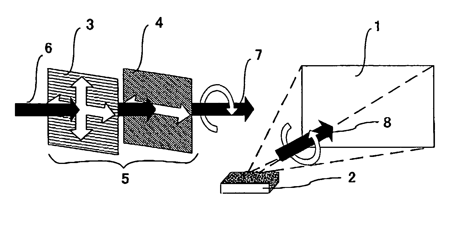
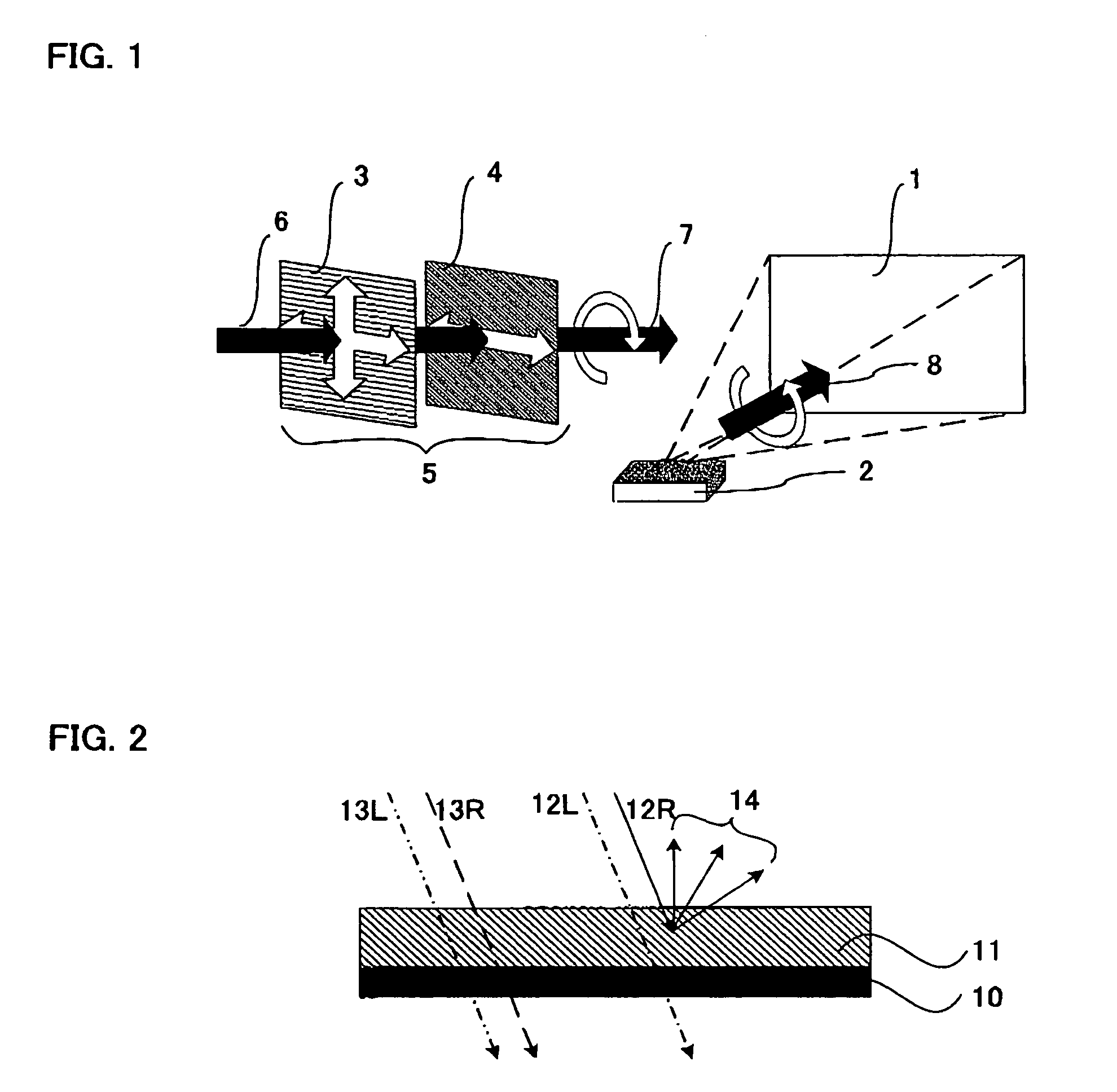
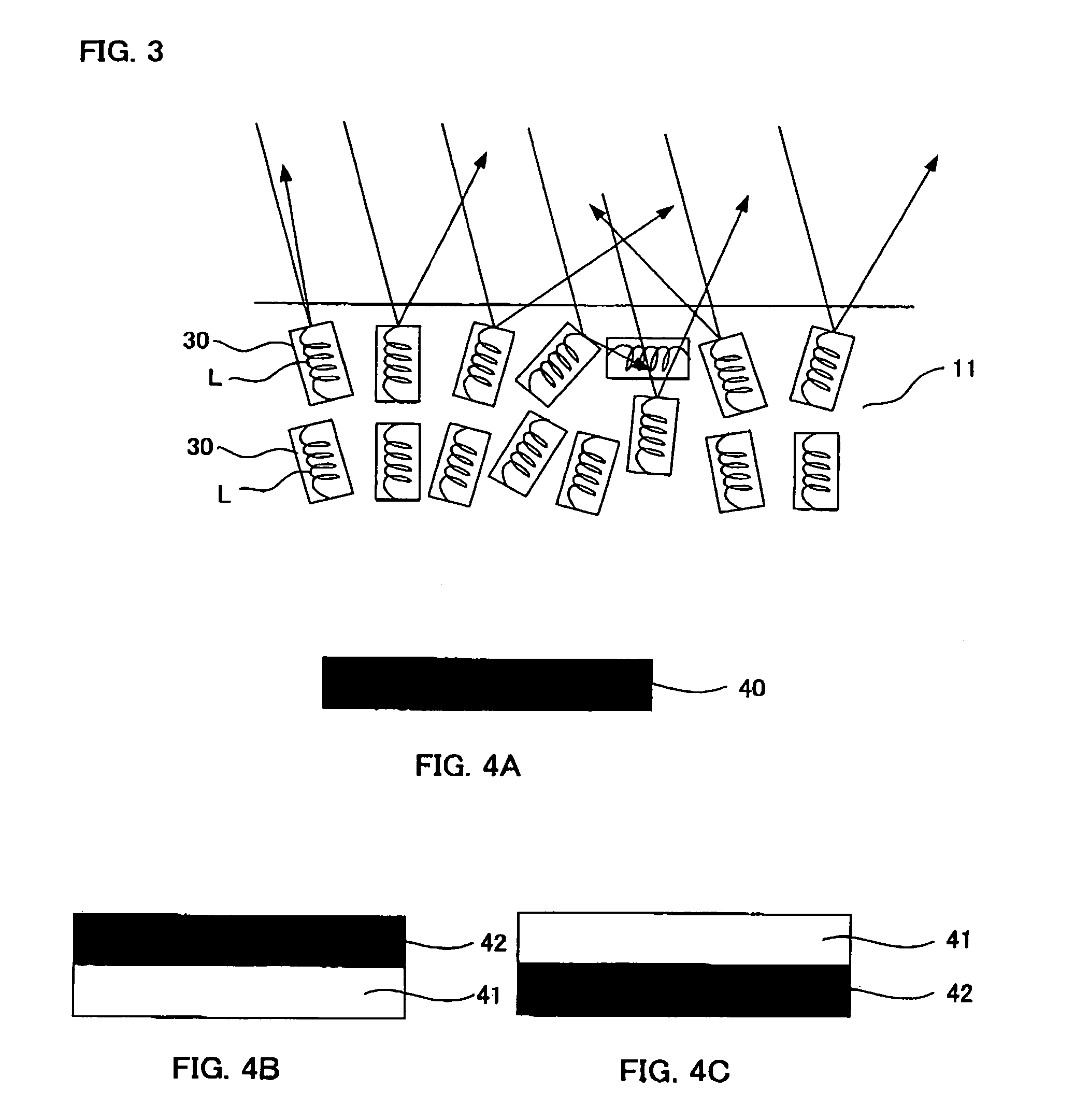
[0012]In the present invention, the polarized light selective-reflection layer has a property of diffuse-reflecting the right-handed circularly polarized light or left-handed circularly polarized light, and the external light screen circularly polarizes the light in reverse direction to the circularly polarized light which is diffuse-reflected by the polarized light selective-reflection layer. Therefore, reflection of external light on the projection screen can be theoretically set to zero, so that only the image light is reflected. As a result, a sharp contrast display can be obtained.
[0013]Further in the present invention, since the transmission axis of the linearly polarizing plate is in horizontal direction, only the light vibrating in the horizontal direction can be transmitted. Therefore, S waves (transversal waves) contained a lot, in the reflected light proceeding into the projection system from the external light entrance, can be widely taken in, and a brighter environment is realized within a range not adversely influenced by the ambient light.
[0018]In the present invention, the circularly polarized light diffuse-reflected by the polarized light selective-reflection layer and the light circularly polarized by the external light screen are in mutually reverse directions. Therefore, reflection of external light on the projection screen can be theoretically set to zero, and only the image light is reflected, so that a display of sharp contrast can be obtained. Further, by making the transmission axis of the linearly polarizing plate, constituting the external light screen, in horizontal direction, S waves (transversal waves) contained a lot in the reflected light can be widely taken in, so that a brighter environment can be realized within a range not adversely influenced by the ambient light.

Problems solved by technology

As a result, in such conventional projection screen, it is difficult to realize a favorable image display unless influence by the ambient light such as external light is suppressed by using a means to darken the room or other environmental means.
However, it does not have polarized light selectivity, and there is a problem that it can only display an image with sharpness of limited degree.
Further, there is a problem that, in the projection screen using hologram, it is difficult to obtain a wide screen because of manufacturing problem.
However, for example, even when the cholesteric liquid crystal, which reflects right-handed circularly polarized light, is used, the right-handed circularly polarized light of the ambient light is reflected, so that sufficient improvement of the contrast cannot be realized in some cases.

Method used


Image

  • Projection system
  • Projection system
  • Projection system

Examples


Embodiment Construction

[0024]Projection system and external screen of the present invention are described below.

A. Projection System

[0025]The projection system of the present invention comprises: a projection screen, containing a substrate and a polarized light selective-reflection layer formed on the substrate and diffuse-reflects right-handed circularly polarized light or left-handed circularly polarized light, which displays an image by reflecting an image light irradiated from a projector; a projector for projecting an image light on the projection screen; and an external light screen installed at an external light entrance, disposed in a sequence of a linearly polarizing plate and a retardation plate from an external side, and circularly polarizes a light in reverse direction to the circularly polarized light diffuse-reflected by the polarized light-selective reflection layer, wherein a transmission axis of the linearly polarizing plate is in horizontal direction.

[0026]In the present invention, the p...


PUM

PropertyMeasurementUnit
wavelengthaaaaaaaaaa

Abstract

Provided is a projection system capable of obtaining a sharp contrast without being influenced by an ambient light, the projection system including a projection screen, containing a substrate and a polarized light selective-reflection layer formed on the substrate that diffuse-reflects right-handed circularly polarized light or left-handed circularly polarized light. An image is displayed by reflecting an image light irradiated from a projector on the projection screen. An external light screen is installed at an external light entrance and disposed in a sequence of a linearly polarizing plate and a retardation plate from an external side, and the external light screen circularly polarizes a light in reverse direction to the circularly polarized light diffuse-reflected by the polarized light-selective reflection layer. A transmission axis of the linearly polarizing plate is in a horizontal direction.

Description

BACKGROUND OF THE PRESENT INVENTION[0001]1. Field of the Present Invention[0002]The present invention relates to a projection system comprising a projection screen, a projector, and an external light screen.[0003]2. Description of the Related Art[0004]A conventional projection system is generally designed to display an incident image light, from a projector, on a projection screen, and an observer observes its reflected light as an image.[0005]Recently, along with downsizing, price-reduction, etc. of the projector main body, demand for use at home, such as home theater system, is increasing, and the projection systems are widely used in general household. In such projection system, image contrast of an image is brought forth by intensity difference of the incident light (image light), from the projector, incident on the projection screen. For example, when displaying a white picture on a black background, the portion of the projection screen lighten by the incident light will be whi...

Claims


Application Information

Patent Timeline
Patent Type & Authority Patents(United States)
IPC IPC(8): G03B21/56F21V9/14G03B21/14G02B5/30G02F1/13G03B21/00G03B21/10G03B21/60G03B21/604
CPCG03B21/604G03B21/2073G03B21/2066H04N5/7416
Inventor MORIYA, NORIHISA
Owner DAI NIPPON PRINTING CO LTD
Learn More