Projection screen and projection system containing same

a projection screen and projection system technology, applied in the field of projection systems, can solve the problems of insufficient image display performance of conventional projection screens, inability to provide good image display, and projection screens using holograms can only display images with limited sharpness, so as to achieve enhanced image contrast, efficient reflection, and improved image visibility

Inactive Publication Date: 2007-01-25
DAI NIPPON PRINTING CO LTD
View PDF6 Cites 1 Cited by
  • Summary
  • Abstract
  • Description
  • Claims
  • Application Information

AI Technical Summary

Benefits of technology

[0022] The present invention has been accomplished under these above-mentioned circumstances. An object of the present invention is therefore to provide a projection screen capable of sharply displaying an image even under bright environmental light and of providing intensified brightness and high visibility, and a projection system containing such a projection screen. (Means for Fulfilling the Object)

Problems solved by technology

However, the above-described conventional projection screens cannot show good image display performance under bright environmental light because the screens reflect not only imaging light but also environmental light such as sunlight and light from lighting fixtures.
For this reason, the conventional projection screen cannot satisfactorily provide good image display unless the influence of environmental light such as sunlight and light from lighting fixtures on the projection screen is suppressed by using a means for shading a room, or by placing the projection screen in a dark environment.
However, holograms have wavelength selectivity but no polarization selectivity, meaning that the projection screens using holograms can display images only with limited sharpness.
Moreover, it is difficult to produce large-sized projection screens by utilizing holograms due to production problems.
However, in the projection screen described in JP '660, since the cholesteric liquid crystal is in the state of planar orientation, specular reflection occurs when the projection screen reflects light, and the reflected light cannot be well recognized as an image.
If these planes of polarization do not agree with each other, excellent image display cannot be attained.
However, since the diffusing element for scattering the reflected light is provided on the viewer's side of the reflective polarization element, the polarized-light-separating property of the reflective polarization element is impaired, and image visibility cannot be fully improved.
Because of these two phenomena, the original polarized-light-separating property is impaired, and image visibility cannot be fully improved.
The polarized-light-separating property is impaired also by such anti-glaring layers.
Therefore, it has so far been impossible to fully improve image visibility.

Method used


Image

  • Projection screen and projection system containing same
  • Projection screen and projection system containing same
  • Projection screen and projection system containing same

Examples


example 1

[0207] A first cholesteric liquid crystal solution having a selective reflection wave range centered at 440 nm was prepared by dissolving, in cyclohexanone, a monomer-containing liquid crystal consisting of a main component (94.7% by weight), an ultraviolet-curing nematic liquid crystal, and a polymerizable chiral agent (5.3% by weight). A liquid crystal containing a compound represented by the above chemical formula (2-xi) was used as the nematic liquid crystal. A compound represented by the above chemical formula (5) was used as the polymerizable chiral agent. To the first cholesteric liquid crystal solution, 5% by weight of “Irg 369” available from Ciba Specialty Chemicals K.K., Japan was added as a photopolymerization initiator.

[0208] By a bar coating method, the above-prepared first cholesteric liquid crystal solution was applied to a substrate (“LUMIRROR / AC-X” manufactured by Panac Co., Ltd., Japan) that was a black-colored PET film with a surface area of 200 mm×200 mm, havin...

example 2

[0216]“ADEKA Optomer KRX-559-7” manufactured by ASAHI DENKA KOGYO K.K., Japan was prepared as a material for forming a hard coat layer, and was applied, by a bar coating method, directly to the polarized-light selective reflection layer in the projection screen obtained in Example 1. This coating film was dried at 80° C. for 5 minutes and was then cured by the application of 750 mJ / cm2 of ultraviolet light, thereby forming a hard coat layer with a thickness of 5 μm. There was thus obtained a projection screen containing the hard coat layer laminated to the polarized-light selective reflection layer. The surface hardness of the hard coat layer in the projection screen obtained in this manner was measured. As a result, the pencil hardness of the hard coat layer determined in accordance with JIS K5400 was found to be 2H or more.

example 3

[0217]“ZR-100 (trade name)” manufactured by Sumitomo Osaka Cement Co., Ltd., Japan was prepared as a material for forming an ultraviolet-absorbing layer, and was applied, by a spin coating method, directly to the polarized-light selective reflection layer in the projection screen obtained in Example 1. This coating film was dried at 80° C. for 1 minute, thereby obtaining an ultraviolet-absorbing layer whose thickness was approximately 2 μm. Thus, there was obtained a projection screen in which the ultraviolet-absorbing layer was laminated to the polarized-light selective reflection layer.


PUM


Abstract

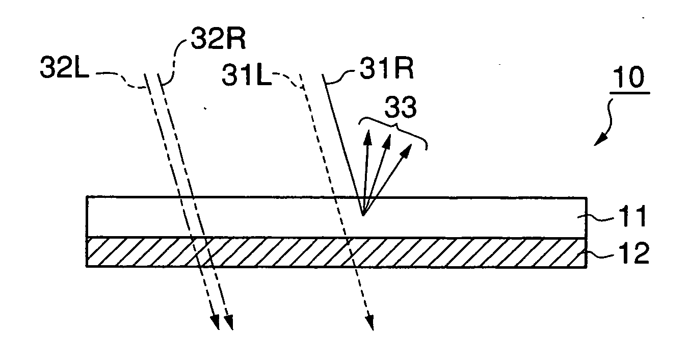
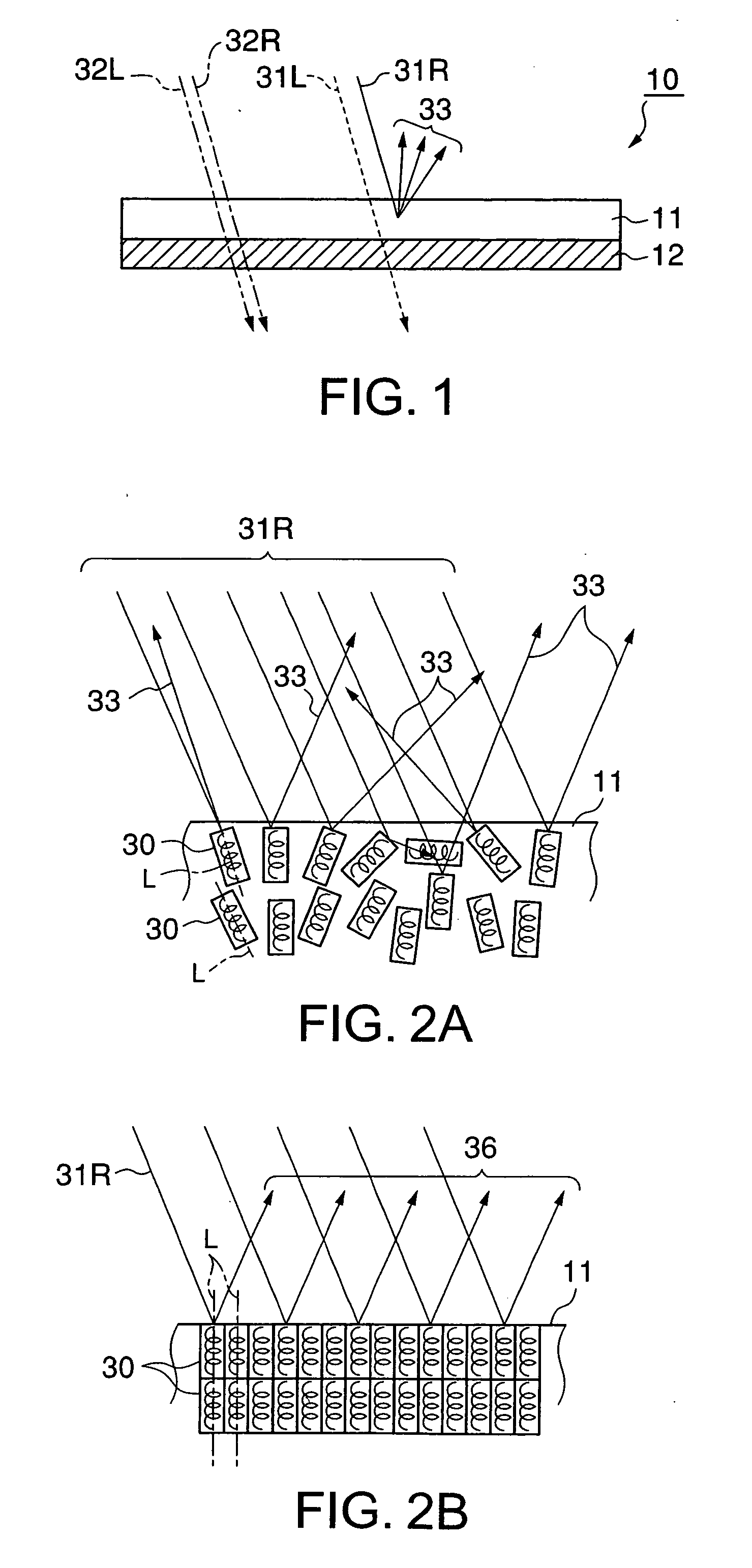
A projection screen capable of sharply displaying an image even under bright environmental light with high image visibility. A projection screen has a polarized-light selective reflection layer with a cholesteric liquid crystalline structure, capable of selectively reflecting a specific polarized light component, and a substrate for supporting the reflection layer. Of the light entering the reflection layer from the viewer's side, the right-handed light in the selective reflection wave range is reflected from the reflection layer as reflected light. As a result of structural non-uniformity in the cholesteric liquid crystalline structure, the light that is selectively reflected (reflected light) is diffused.

Description

[0001] This is a Continuation of application Ser. No. 10 / 864,876 filed Jun. 10, 2004. The entire disclosure of the prior application is hereby incorporated by reference in its entirety.BACKGROUND OF THE INVENTION [0002] 1. Field of the Invention [0003] The present invention relates to a projection system in which imaging light emitted from a projector is projected on a projection screen to display thereon an image. More particularly, the present invention relates to a projection screen capable of sharply displaying an image and of providing high visibility, and to a projection system containing such a projection screen. [0004] 2. Description of Related Art [0005] A conventional projection system usually operates as follows: imaging light emitted from a projector is projected on a projection screen, and viewers observe the light reflected from the projection screen as an image. [0006] Typical examples of projection screens for use in such conventional projection systems include white...

Claims


Application Information

Patent Timeline
Patent Type & Authority Applications(United States)
IPC IPC(8): G03B21/56G02B5/30G03B21/60
CPCG02B5/3016G03B21/604G03B21/60
Inventor UMEYA, MASANORI
Owner DAI NIPPON PRINTING CO LTD
Why Eureka
Try Eureka