Al technical title is built by PatSnap Al team. It summarizes the technical point description of the patent document.
a surgical device and clamping mechanism technology, applied in the field of linear clamping, cutting and stapling, can solve the problem that the opposing jaws of the clamping mechanism do not provide adequate clamping
Inactive Publication Date: 2010-06-29
TYCO HEALTHCARE GRP LP
View PDF616 Cites 1960 Cited by
Summary
Abstract
Description
Claims
Application Information
AI Technical Summary
This helps you quickly interpret patents by identifying the three key elements:
Problems solved by technology
Method used
Benefits of technology
[0008]By biasing the distal ends of the first and second jaws towards each other, the surgical device may, in accordance with one example embodiment of the present i
Problems solved by technology
One problem with the foregoing surgical devices, and in particular with the foregoing linear clamping, cutting and stapling devices such as that illustrated in FIG. 1, is that the opposing jaws of the clamping mechanism do not provide ad
Method used
Image
Click on the blue label to locate the original text in one second.
Reading with bidirectional positioning of images and text.
Examples
Embodiment Construction
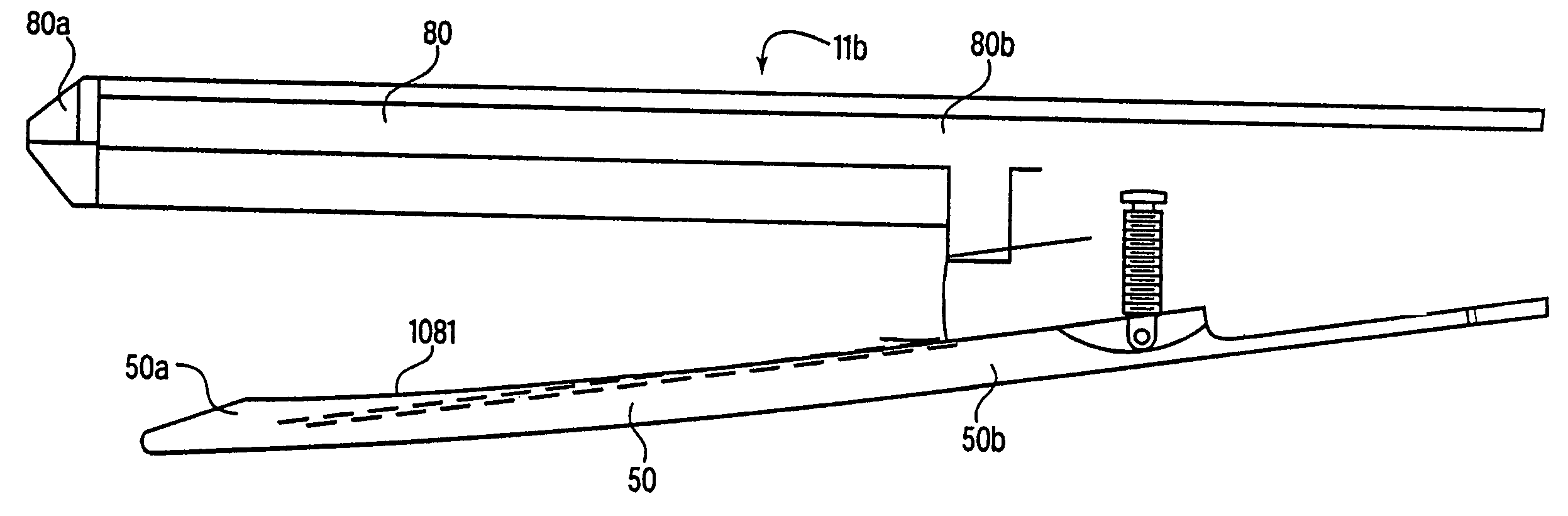
[0035]One example embodiment of a surgical device according to the present invention is schematically illustrated in FIGS. 3(a) to 3(d). Referring to FIGS. 3(a) to 3(d), an example embodiment of the surgical device 11a, e.g., a linear clamping, cutting and stapling device, is illustrated. In this embodiment, a surgical device 11a includes a first jaw 50 having a distal end 50a and a proximal end 50b, and a second jaw 80 having a distal end 80a and a proximal end 80b. The first jaw 50 and the second jaw 80 are pivotably coupled at or near their respective proximal ends 50b, 80b. The proximal end 50b of the first jaw 50 and the proximal end 80b of the second jaw 80 are biased away from each other via a biasing element 82. In this example embodiment, the biasing element 82 may be a spring. The surgical device 11a includes a stop element that limits the distance that the proximal end 50b of the first jaw 50 can be separated from the proximal end 80b of the second jaw 80. In the example ...
PUM
Property
Measurement
Unit
Force
aaaaa
aaaaa
Abstract
A surgical device that includes a first jaw having a distal end and a second jaw having a distal end. The second jaw is disposed in opposed correspondence with the first jaw. The first jaw is pivotably coupled to the second jaw. The surgical device also includes a biasing element, such as a spring, that biases the distal end of the first jaw towards the distal end of the second jaw. The device may also include a first driver disposed in the second jaw and coupled to the first jaw. The first driver is configured to cause separation of the first jaw and the second jaw when the first driver is actuated for opening the jaws and to close the first jaw and the second jaw when the first driver is actuated for closing the jaws. The device may also include at least one of a cutting element and a stapling element disposed within the second jaw, preferably a blade rotatably mounted on a wedge. A second driver is configured to move the cutting element and/or the stapling element proximally from a distal end toward the proximal end of the second jaw to at least one of cut and staple a section of tissue disposed between the first and second jaws. By biasing the distal ends of the first and second jaws towards each other, the surgical device may prevent a section of tissue which is disposed between the first and second jaws from escaping out from between the distal ends of the first and second jaws.
Description
CROSS-REFERENCE TO RELATED APPLICATIONS[0001]The present application expressly incorporates herein by reference each of the following in its entirety: U.S. Patent Application Ser. No. 60 / 388,644, filed on Jun. 14, 2002; U.S. patent application Ser. No. 09 / 999,546, filed on Nov. 30, 2001; U.S. patent application Ser. No. 09 / 887,789, filed on Jun. 22, 2001; U.S. patent application Ser. No. 09 / 836,781, filed on Apr. 17, 2001; U.S. patent application Ser. No. 09 / 723,715, filed on Nov. 28, 2000; U.S. patent application Ser. No. 09 / 324,451, filed on Jun. 2, 1999; U.S. patent application Ser. No. 09 / 324,452, filed on Jun. 2, 1999; U.S. patent application Ser. No. 09 / 351,534, filed on Jul. 12, 1999 and issued as U.S. Pat. No. 6,264,087 on Jul. 24, 2001; U.S. patent application Ser. No. 09 / 510,923, filed on Feb. 22, 2000; and U.S. patent application Ser. No. 09 / 510,927, filed on Feb. 22, 2000.FIELD OF THE INVENTION[0002]The present invention relates to a surgical device. More specifically, t...
Claims
Application Information
Patent Timeline
Application Date:The date an application was filed.
Publication Date:The date a patent or application was officially published.
First Publication Date:The earliest publication date of a patent with the same application number.
Issue Date:Publication date of the patent grant document.
PCT Entry Date:The Entry date of PCT National Phase.
Estimated Expiry Date:The statutory expiry date of a patent right according to the Patent Law, and it is the longest term of protection that the patent right can achieve without the termination of the patent right due to other reasons(Term extension factor has been taken into account ).
Invalid Date:Actual expiry date is based on effective date or publication date of legal transaction data of invalid patent.