
Board-to-board connector assembly

a board-to-board connector and connector technology, applied in the direction of fixed connections, electrical discharge lamps, coupling device connections, etc., can solve the problems of unsteady contact and affect the electrical connection between the printed circuit boards, and achieve the effect of steady electrical connection

Inactive Publication Date: 2010-07-06
CHENG UEI PRECISION IND CO LTD
View PDF7 Cites 39 Cited by
  • Summary
  • Abstract
  • Description
  • Claims
  • Application Information

AI Technical Summary

Benefits of technology

The present invention provides a board-to-board connector assembly for electrically interconnecting female and male printed circuit boards. The assembly includes a receptacle connector and a plug connector. The receptacle connector has first terminals with a resilient portion for soldering to the female printed circuit board. The plug connector has second terminals soldered to the male printed circuit board. The assembly utilizes the resilient portions of the first and second terminals to ensure a steady contact between the two printed circuit boards, resulting in a reliable electrical connection.

Problems solved by technology

However, with the development of electronic field, the board-to-board connector assembly is microminiaturized more and more so that the distance between the printed circuit boards may be longer or shorter than a standard distance due to the manufacturing or assembly inaccuracy.
As a result, that leads the plug connector to be improperly engaged with the receptacle connector and further results in an unsteady contact between the first terminal and the corresponding second terminal so that affects the electrical connection between the printed circuit boards.

Method used


Image

  • Board-to-board connector assembly
  • Board-to-board connector assembly
  • Board-to-board connector assembly

Examples


Embodiment Construction

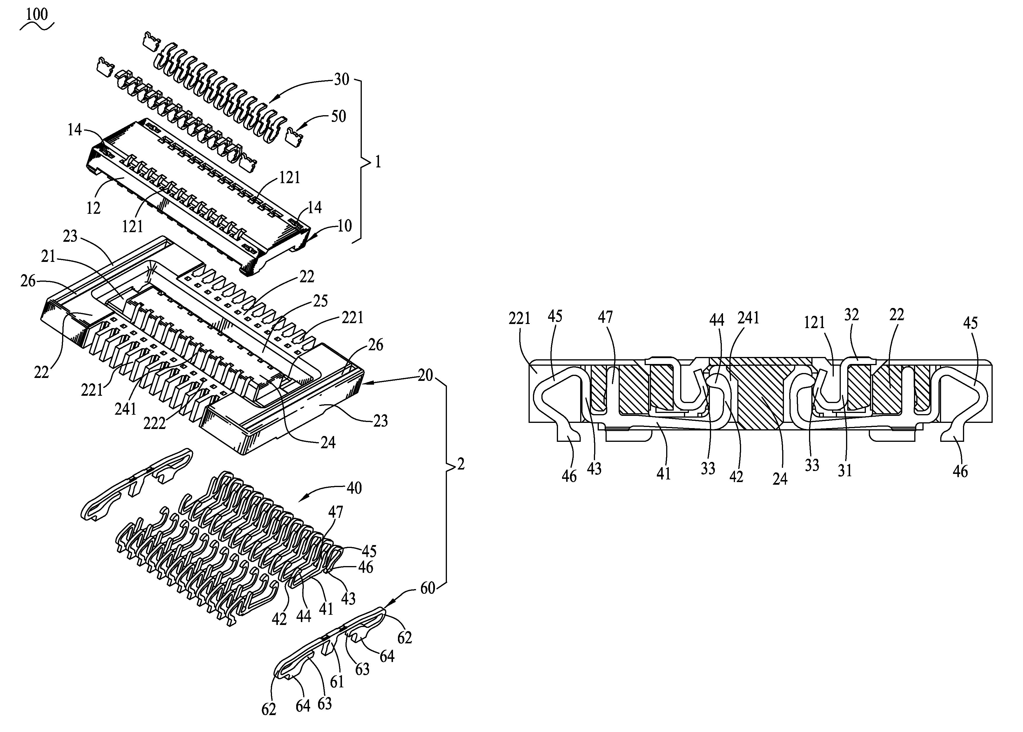
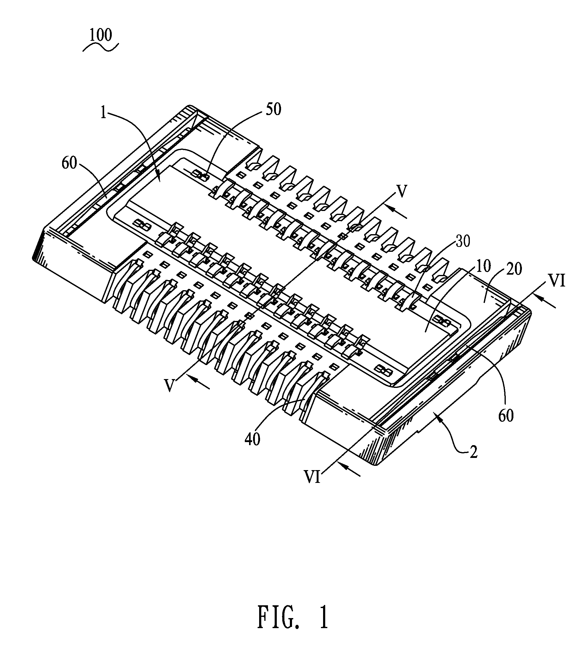
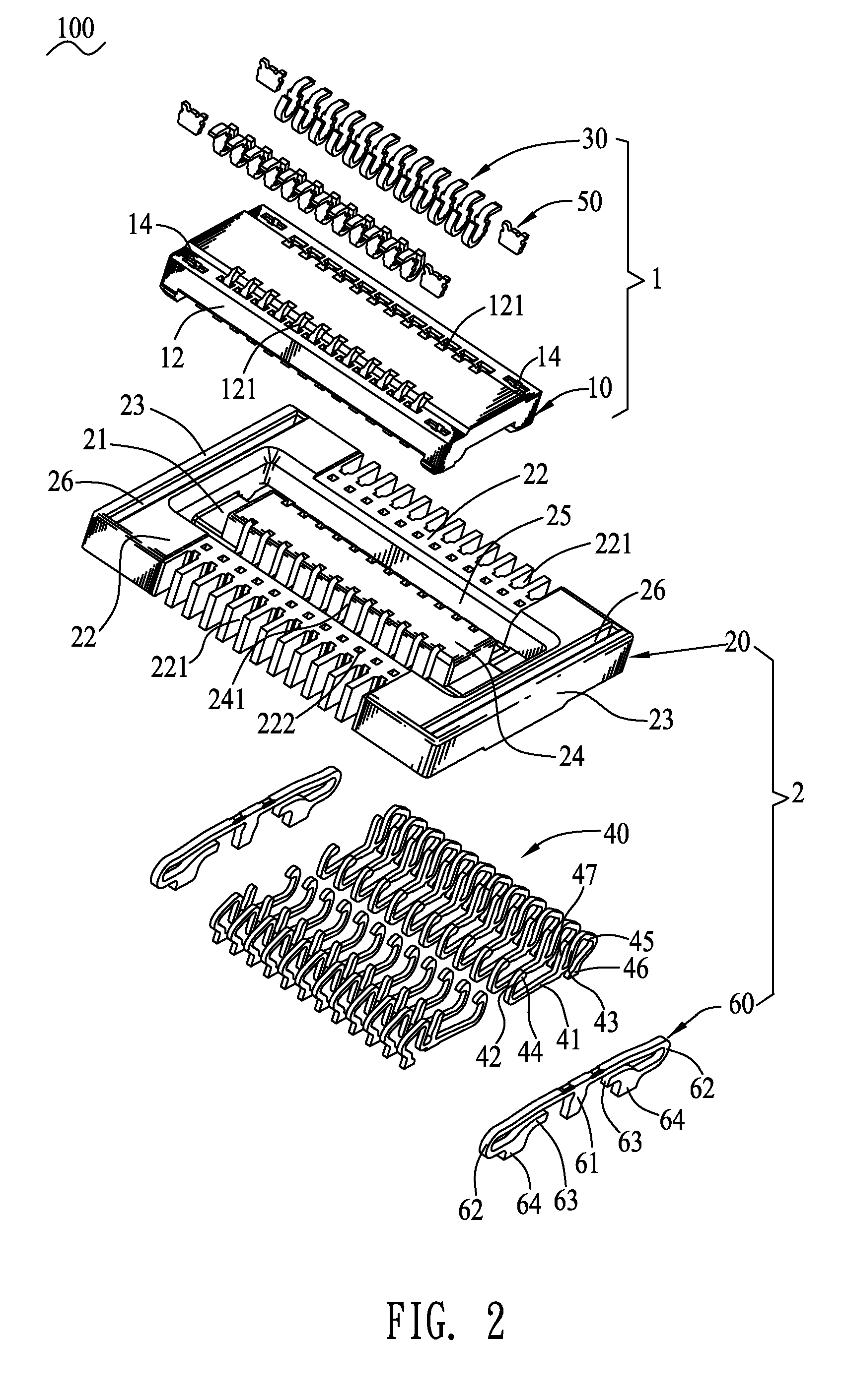
[0014]With reference to FIG. 1 and FIG. 2, a board-to-board connector assembly 100 in accordance with the present invention includes a receptacle connector 2 and a plug connector 1 which can be mounted to a pair of spaced parallel female and male printed circuit boards (not shown) to electrically interconnect the printed circuit boards, wherein the plug connector 1 is mated with the receptacle connector 2. The receptacle connector 2 includes a receptacle housing 20, a plurality of first terminals 40 and a pair of fixing members 60 disposed in the receptacle housing 20 respectively.

[0015]Referring to FIGS. 2 and 4, the receptacle housing 20 has a rectangular flat base board 21. Two opposite sides of the base board 21 extend upward to form a pair of first sidewalls 22 extending longwise. Two opposite ends of the base board 21 extend upward to form a pair of second sidewalls 23. A middle of the base board 21 protrudes upward to form a rectangular inserting rib 24 extending longwise and...


PUM


Abstract

A board-to-board connector assembly includes a receptacle connector and a plug connector. The receptacle connector includes a receptacle housing, a plurality of first terminals and at least one fixing member disposed in the receptacle housing respectively. Each of the first terminals has a crooked first resilient portion and a soldering portion protruded from a free end of the first resilient portion to further project under the receptacle housing. The fixing member has a pair of crooked second resilient portions and two soldering tails each protruded from a free end of the respective second resilient portion to further project under the receptacle housing. The plug connector includes a plug housing mated with the receptacle housing, and a plurality of second terminals disposed in the plug housing and electrically contacting the corresponding first terminals.

Description

BACKGROUND OF THE INVENTION[0001]1. Field of the Invention[0002]The present invention generally relates to an electrical connector, and more particularly to a board-to-board connector assembly.[0003]2. The Related Art[0004]Generally, a board-to-board connector assembly includes a receptacle connector and a plug connector mounted to a pair of spaced parallel printed circuit boards for electrically interconnecting the printed circuit boards. The receptacle connector includes a plurality of first terminals for being soldered to one printed circuit board. The plug connector includes a plurality of second terminals for being soldered to the other printed circuit board. When the plug connector is mated with the receptacle connector, the first terminal electrically contact the corresponding second terminal so as to form an electrical connection between the printed circuit boards. However, with the development of electronic field, the board-to-board connector assembly is microminiaturized m...

Claims


Application Information

Patent Timeline
Patent Type & Authority Patents(United States)
IPC IPC(8): H01R12/00
CPCH01R13/6315H01R12/716H01R12/57H01R12/707
Inventor PENG, YUNG-CHIYU, SHENG-NAN
Owner CHENG UEI PRECISION IND CO LTD
Learn More