Method for reducing hydrocarbon emissions

a technology of hydrocarbons and emissions, applied in the field of reducing hydrocarbon emissions, can solve the problems of difficult and expensive to deal with these types of emissions, and achieve the effect of reducing the “potential to emit”

Inactive Publication Date: 2010-07-06
HAGELSTON AMY JANEEN +2
View PDF7 Cites 33 Cited by
  • Summary
  • Abstract
  • Description
  • Claims
  • Application Information

AI Technical Summary

Benefits of technology

[0034]The recovery of the products and the subsequent combustion / oxidation of the vapors of the VOC's, further reduces the “potential to emit”.

Problems solved by technology

Pipeline operations also generally cover considerable distances, making it difficult and expensive to deal with these types of emissions.
Venting and flaring have long been accepted and unquestioned practices in the refining and chemical industries.

Method used


Image

  • Method for reducing hydrocarbon emissions
  • Method for reducing hydrocarbon emissions
  • Method for reducing hydrocarbon emissions

Examples


Embodiment Construction

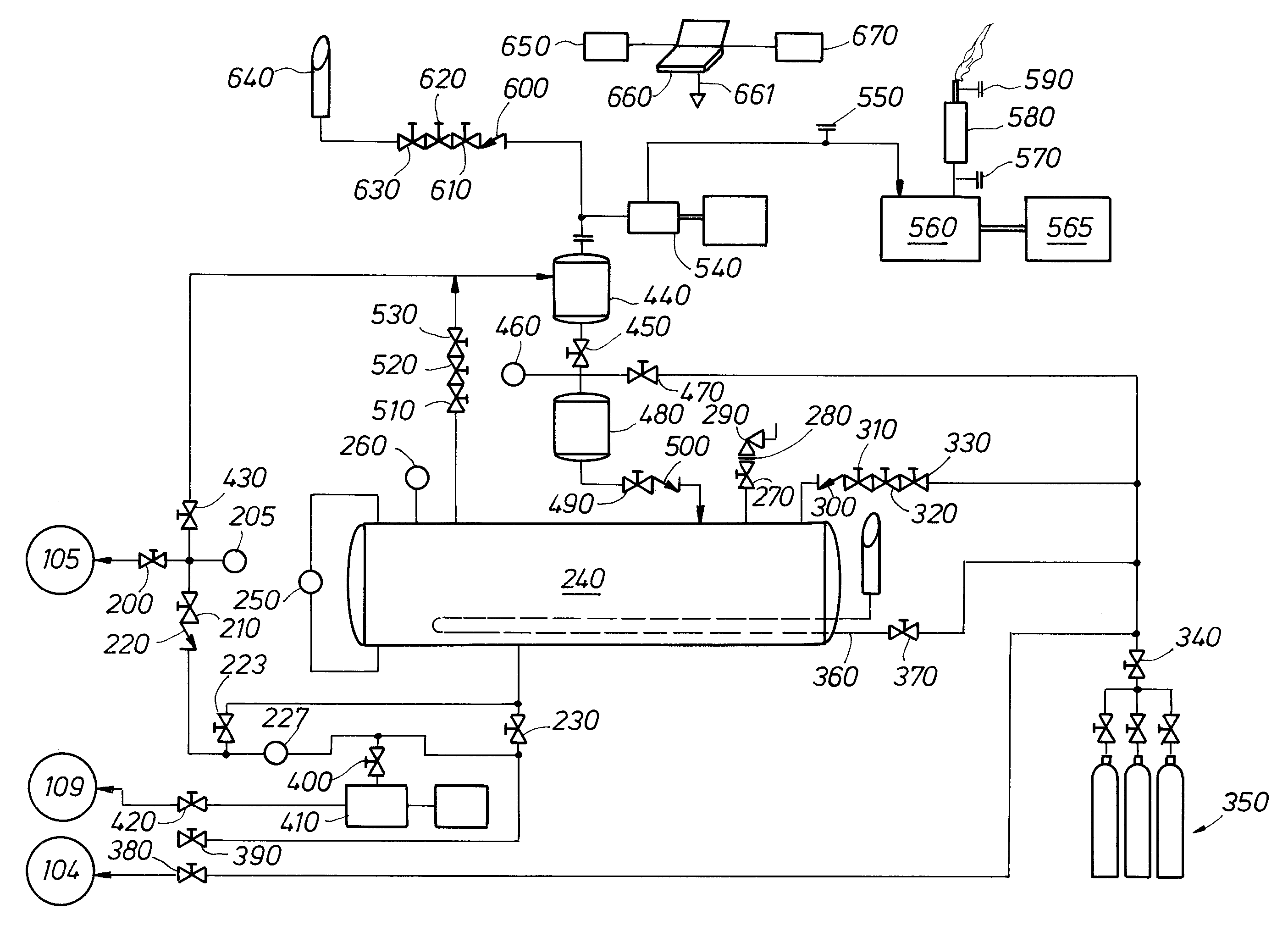
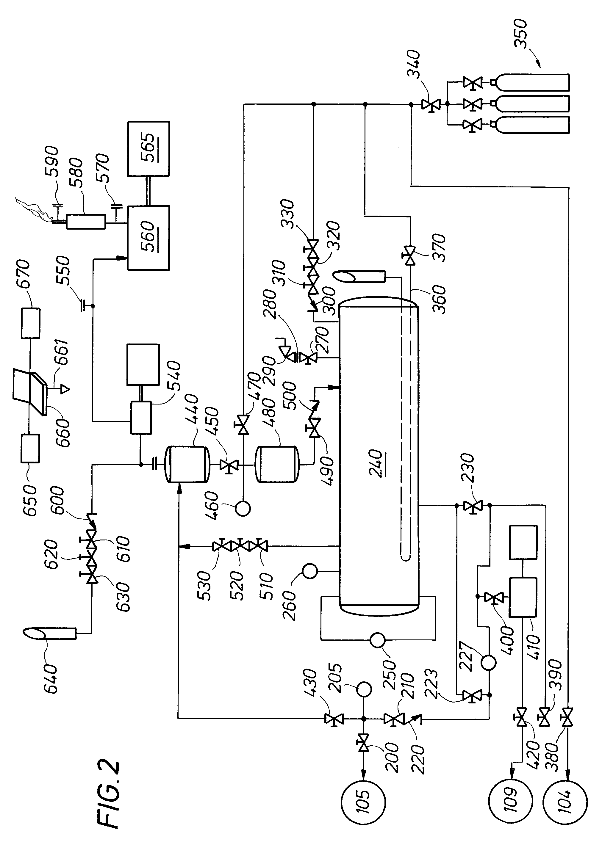
[0037]Advantageously, the present invention provides for the reduction of venting and flaring in pipeline operations associated with oil and gas production and petrochemical manufacturing and refining. This is accomplished by operating several systems together to accomplish the stated objectives of: i) reducing venting and flaring to the atmosphere; ii) maximizing product recovery; iii) documenting the operation to assure regulatory agencies that objectives were accomplished.

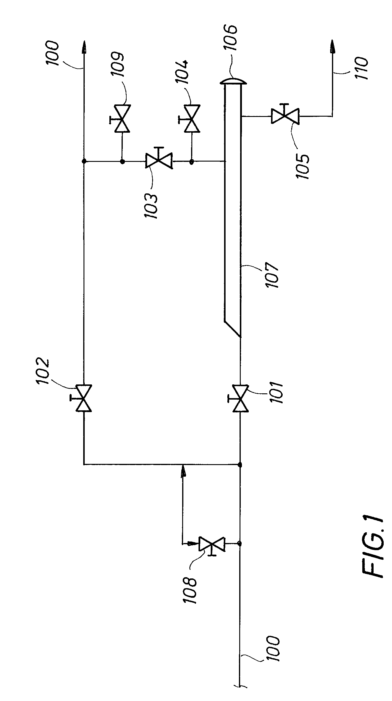
[0038]An example is used below of a “pigging” operation, where a “pig” or “swab” is received into a pipeline “pig trap”. A pig trap is a system of piping and valves constructed to receive a “pig” or “swab” and is generally arranged as shown in FIG. 1. While the example shows a pertinent application of the invention, the example is only one of many areas of application of the invention.

Description of Normal Pig Trap Operation

[0039]In normal operation of a pipeline 100, a trap bypass valve 102 is open and a trap v...


PUM

PropertyMeasurementUnit
pressureaaaaaaaaaa
pressureaaaaaaaaaa
lengthaaaaaaaaaa

Abstract

A system for recovering and recycling otherwise vented or flared volatile and non-volatile reactive organic materials from pipeline and plant operations associated with oil and gas recovery, refining and petrochemical manufacture, processing and transportation includes a means to remove and store volatile hydrocarbons for a portion of a system or pipeline.

Description

[0001]This application claims the benefit of U.S. Provisional Patent Application No. 60 / 755,929 filed Jan. 3, 2006.FIELD OF THE INVENTION[0002]The invention relates generally to reducing emissions of volatile compounds. More particularly, the invention is a method for reducing emissions of highly reactive volatile organic compounds from pipeline operations associated with oil and gas recovery, production, refining, and petrochemical manufacture, processing, and transportation.BACKGROUND OF THE INVENTION[0003]Many oil, gas, and petrochemical pipeline operations, including pigging, swabbing, changes of meter parts, pipeline inspection maintenance (PIM), and the like, produce emissions of volatile organic compounds in associated venting or flaring operations. Pipeline operations also generally cover considerable distances, making it difficult and expensive to deal with these types of emissions.[0004]Over the past few years, there has been more and more regulation of emissions of contam...

Claims


Application Information

Patent Timeline
Patent Type & Authority Patents(United States)
IPC IPC(8): B01D19/00
CPCB08B9/055B08B15/00Y10T137/3003
Inventor MCCULLY, TIM
Owner HAGELSTON AMY JANEEN
Why Eureka
Try Eureka