Thighbone shaft

a technology of thighbone shaft and thighbone, which is applied in the field of thighbone shaft, can solve the problems of large area of thighbone damage, large area of wounds, and the inability of the thighbone shaft to meet users' needs, and achieve the effects of reducing the size of the planted thighbone shaft, reducing the stress force, and relatively small wound area

Inactive Publication Date: 2010-07-13
LUNG CHEN YU +1
View PDF8 Cites 21 Cited by
  • Summary
  • Abstract
  • Description
  • Claims
  • Application Information

AI Technical Summary

Benefits of technology

[0009]Accordingly, an object of the present invention is to provide a thighbone shaft, which has a pole, a head arranged on a front portion of the pole, and a bolt mounted on an inclined threaded hole in the pole, whereby the stress force portion of the thighbone, namely thighbone neck, remains. A thighbone neck acts as a planting point, damaging small area of the thighbone. Only thighbone and acetabulum which have worn-out cartilage need to be replaced, and therefore wound area is relatively small, size of planted thighbone shaft is reduced, stress force decreases, and convenience and utility increases.
[0010]Another object of the present invention is to provide a thighbone shaft, wherein only a head thereof need to be replaced rather than the overall thighbone shaft after long term of use, thereby reducing cost and making operation easier.
[0011]A further object of the present invention is to provide a thighbone shaft, which has tooth portions on opposite sides of the pole thereof for increasing contact area of planting and forming lock structure, thereby promoting planting fixedness.
[0012]A thighbone shaft of the present invention comprises a pole and a bolt. The pole defines an inclined threaded hole therein. Tooth portions are respectively formed at opposite sides of the pole. A head is arranged on a front portion of the pole. A sleeve is provided on a front portion of the head. The bolt forms a threaded portion for fitting in the inclined threaded hole thereby engaging the bolt with the pole. Thus, the thighbone shaft is assembled easily, simultaneously reducing planting area and replacement cost, decreasing stress force, and promoting planting fixedness.

Problems solved by technology

However, this design damages large area of thighbone and produces large area of wound.
Such a thighbone shaft cannot meet users' need.

Method used


Image

  • Thighbone shaft
  • Thighbone shaft
  • Thighbone shaft

Examples


first embodiment

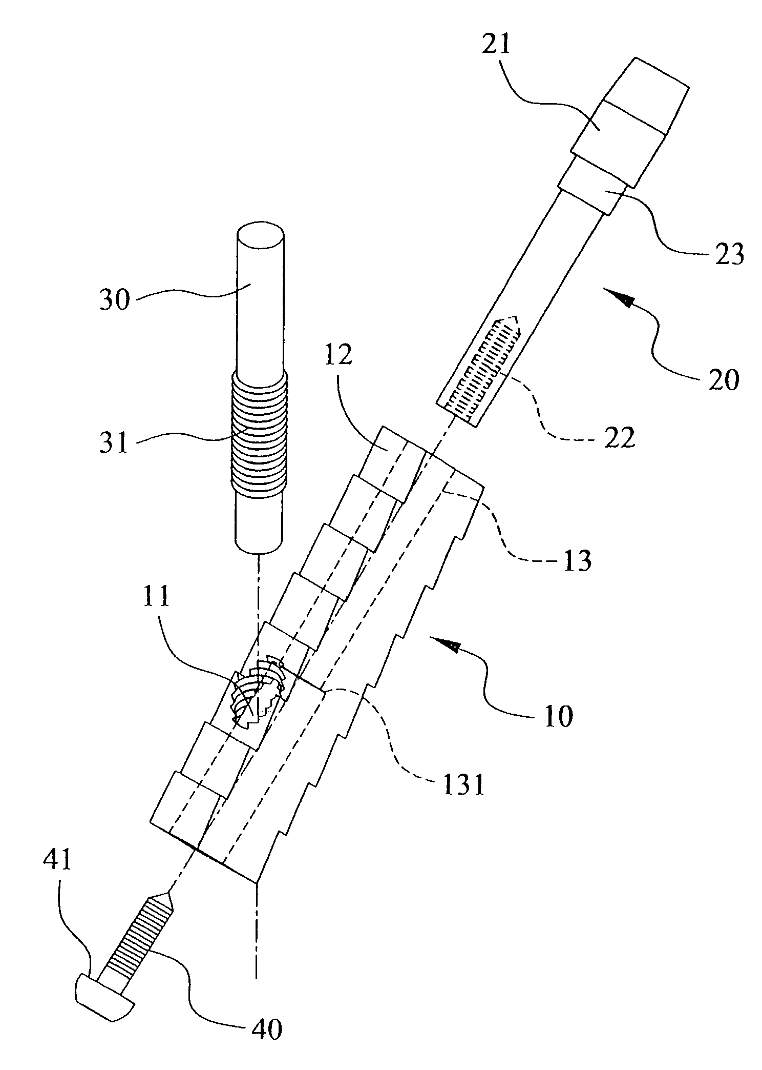
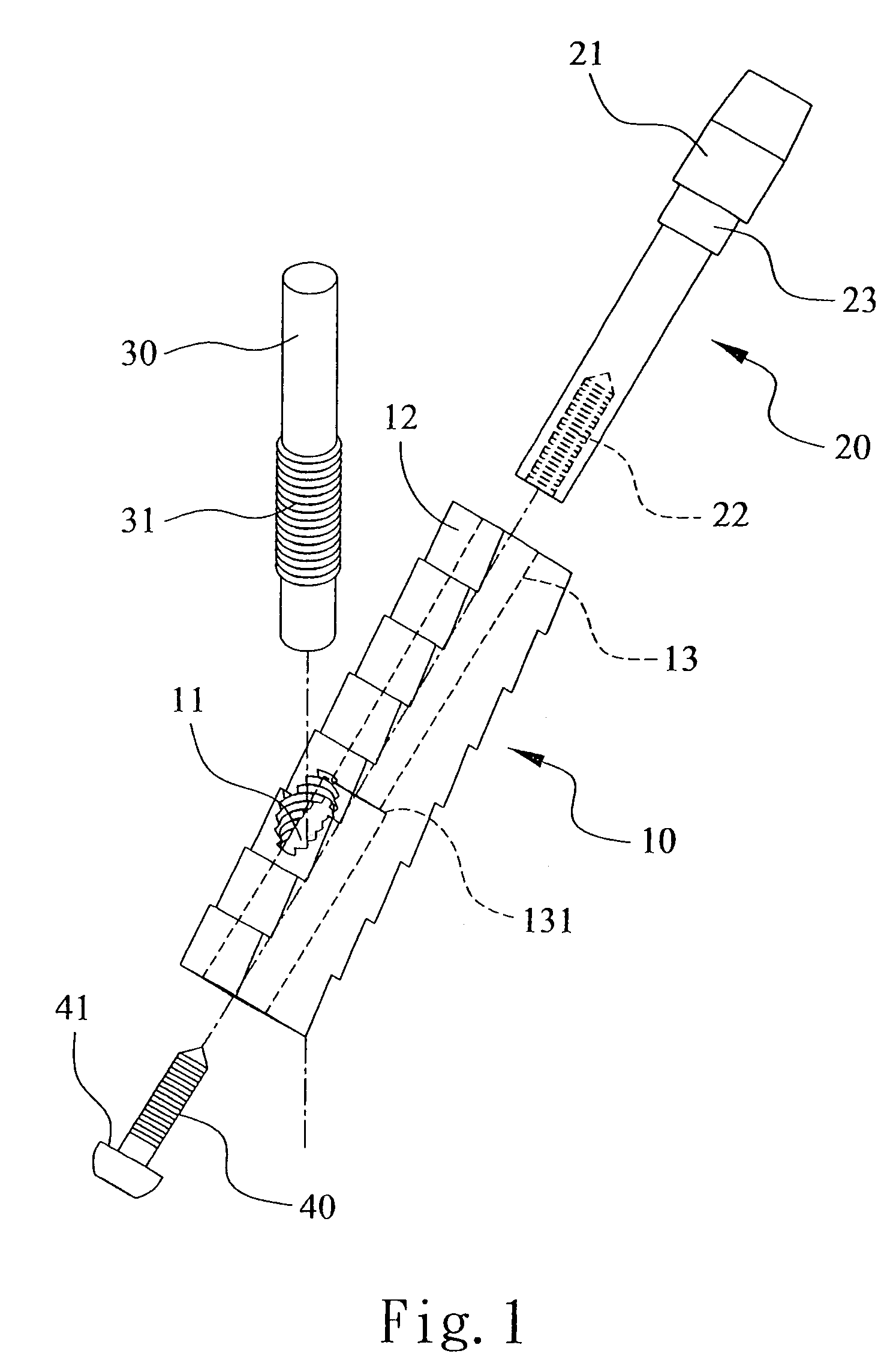
[0020]With reference to FIGS. 1 to 4, a thighbone shaft of the present invention comprises a pole 10, a head 20 mounted on the pole 10, and a separate bolt 30. The pole 10 defines an inclined threaded hole 11 therein. Tooth portions 12 are respectively formed at opposite sides of the pole 10. A through hole 13 is longitudinally defined through a center of the pole 10. A step 131 is formed in the through hole 13.

[0021]The head 20 has a rear end fixed on the through hole 13, and a front end beyond the pole 10. The head 20 defines a positioning hole 22 in the rear end thereof for engaging firmly with a fixing element 40. The fixing element 40 forms a shoulder 41 for abutting with the step 131 in the through hole 13. A sleeve 21 is provided on the front end of the head 20. The head 20 forms a projection 23 at rear of the sleeve 21 for abutting a front surface of the pole 10.

[0022]The bolt 30 forms a threaded portion 31 for fitting in the inclined threaded hole 11 of the pole 10, thereby...

second embodiment

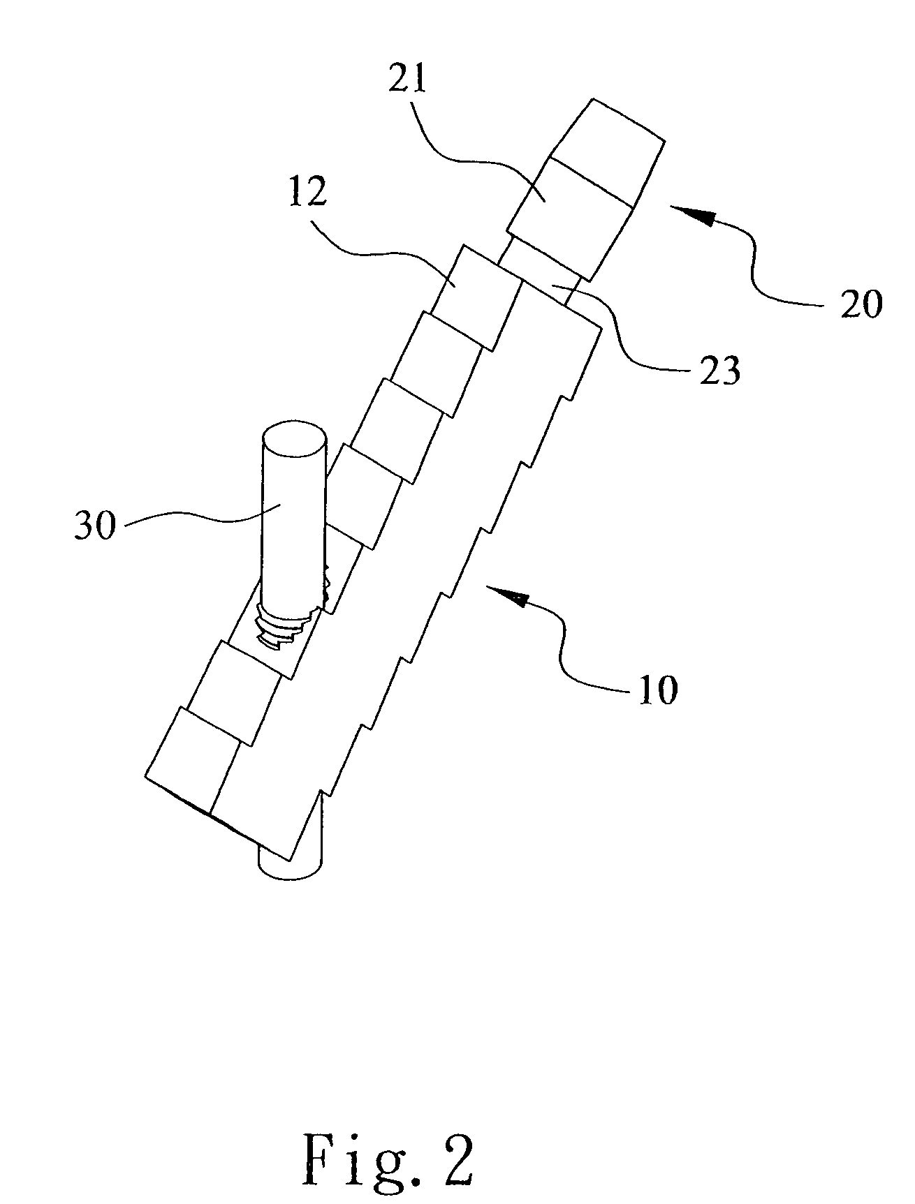
[0025]Referring to FIGS. 6 and 7, according to the present invention, the pole 10 defines an inclined threaded hole 11 therein. Tooth portions 12 are respectively formed at opposite sides of the pole 10. The head 20 and the pole 10 are integrally formed. A sleeve 21 is provided on the front end of the head 20. The bolt 30 forms a threaded portion 31 for fitting in the inclined threaded hole 11 of the pole 10, thereby engaging the bolt 30 with the pole 10. This assembly process is easy. The present invention reduces planting area and stress force and increasing planting fixedness. So it is rather useful and convenient.


PUM


Abstract

A thighbone shaft has a pole and a bolt. The pole defines an inclined threaded hole therein. Tooth portions are respectively formed at opposite sides of the pole. A head is arranged on a front portion of the pole. A sleeve is provided on the head. A threaded portion is formed on the bolt and is retained in the inclined threaded hole for engaging the bolt and the pole. The thighbone shaft is assembled easily, reduces planting area and replacement cost, decreases stress force, and promotes planting fixedness.

Description

BACKGROUND OF THE INVENTION[0001](a) Field of the Invention[0002]The present invention relates to a thighbone shaft, and particularly to a thighbone shaft which has a pole and a bolt mounted on an inclined threaded hole in the pole and which is adapted for artificial joint or the similar.[0003](b) Description of the Prior Art[0004]As disclosed in Taiwan Patent No. 89219012, a conventional artificial joint has a thighbone shaft, which is made of titanium alloy and plants into a user's thighbone. The thighbone shaft comprises:[0005]a front portion, which shrinks gradually and is covered by an adhesion layer and a coating layer, a neck portion connecting with an end of the front portion, a sleeve portion connecting with the neck portion;[0006]a middle portion connecting with an end of the front portion and opposite to the neck portion, and forming a rough surface;[0007]a tail portion connecting with an end of the middle portion, and forming a polishing surface, symmetric grooves being ...

Claims


Application Information

Patent Timeline
Patent Type & Authority Patents(United States)
IPC IPC(8): A61F2/36
CPCA61B17/744A61F2/3601A61F2002/30153A61F2002/30332A61F2002/30354A61F2002/30405A61F2002/30433A61F2002/30434A61F2002/30604A61F2002/30774A61F2002/30782A61F2002/30787A61F2002/30794A61F2002/30797A61F2002/30878A61F2002/30904A61F2002/3625A61F2002/365A61F2220/0025A61F2220/0033A61F2220/0041A61F2230/0019A61F2002/3079
Inventor CHEN, TAIN-HSIUNGLUNG, CHEN-YU
Owner LUNG CHEN YU
Why Eureka
Try Eureka