Flooding reduction method

a technology of flood reduction and flood prevention, applied in data switching networks, frequency-division multiplexes, instruments, etc., can solve problems such as increased probability, network receiving mac frames that are unnecessary, and interconnection bridge bands that may be compressed, so as to reduce flooding in the backbone network

Active Publication Date: 2010-07-13
NIPPON TELEGRAPH & TELEPHONE CORP
View PDF20 Cites 9 Cited by
  • Summary
  • Abstract
  • Description
  • Claims
  • Application Information

AI Technical Summary

Benefits of technology

[0015]According to an aspect of the invention, there is provided a MAC (media access control) frame transfer method for reducing a flooding in a backbone network with which a plurality of customer local area networks are connected via respective edge bridges which each comprise at least one customer port and at least one backbone port to realize a VLAN (virtual local area network). The method comprising the steps of receiving a MAC frame from one of the customer local area networks via the at least one customer port of each edge bridge; identifying a service VLAN ID for the MAC frame from a customer port which received the MAC frame; obtaining a destination group ID for identifying a combination of a source of the MAC frame and at least one destination; on the basis of the obtained destination group ID, judging whether the at least one backbone port includes one which is to transfer the MAC frame; if the at least one backbone port includes at least one backbone port which is to transfer the MAC frame, forming a backbone MAC frame which includes the MAC frame and the service VLAN ID; setting the destination group ID in the backbone MAC frame; and transferring the backbone MAC frame with the destination group ID set to the at least one backbone port which is to transfer the MAC frame.
[0030]According to still another aspect of the invention, there is provided a system for reducing the flooding, in the backbone network, of a virtual LAN realized by connecting a plurality of customer LAN's with the backbone network via respective edge bridges as each described in the just above paragraph.

Problems solved by technology

If a bridge receives, in a network provided through bridges, a MAC (media access control) frame whose destination address is a broadcast address, an unknown multicast address or an unknown unicast address, then the bridge broadcasts (or simultaneously sends) the MAC frame to all of the other ports than the port that has received the MAC frame This disadvantageously increase a probability that terminals connected to the network will receive MAC frames unnecessary for the terminals to receive, which causes a problem that links interconnecting the bridges may have their bands compressed due to the unnecessary MAC frames.
In the GARP, exchanging attributes with the neighboring bridges enables knowing a neighboring bridge to which a received MAC frame which has a specific multicast address as the destination address or which belongs to a known VLAN should be transferred, which results in unnecessary MAC frames not being sent to any other neighboring bridges.
However, this method is disadvantageous in that each of the bridges on the routes has to have a control protocol for this installed and has to exchange information with each other.
However, this method is disadvantageous in that it is difficult to implement this method in bridges in which a higher-speed transfer is required because a process of snooping into the routing information exchanged in an upper layer is a heavy load to such bridges.
Also, it is another problem that a satisfactory effect can not be expected unless all of the bridges on the routes participate in this method as in case of the GARP.
Due to the above-mentioned disadvantages and problems, in the current situation, it is hard to say that such methods as the GARP and the IGMP snooping are widely used as the flooding reduction technique in a network provided through bridges.
In particular, there has not been found, among other things, a case in which either of these methods is used in a provider's network which serves a lot of customers and requires higher-speed transfers.
The problem of flooding reduction in a bridge-based network becomes more serious in a VLAN (virtual LAN) service provided by a provider for the customers.
Pursuing the flood reduction in a provider's networks, which have to maintain and process the setting information in a logically separated manner in order to serve many customers, will cause trade-off problems that the transfer process itself becomes a heavy load due to, for example, making tests of the customer's VLAN information which would not be usually made while higher-speed transfers are required.
Also, if no flooding reduction measures are taken, unnecessary flooding MAC frames have to be transferred in the edge bridges and the backbone bridges, disadvantageously affecting the other customers' transfer processes.
Further, since customer or subscriber lines are generally narrower in the band as compared with backbone lines or customer's premise networks and the band width varies drastically depending on the customer's locations, if flooding of MAC frames occurred in a location of a broader band flows into a location of a narrower band, the communications of the narrower-band location will be disturbed due to unnecessary traffics.

Method used


Image

  • Flooding reduction method
  • Flooding reduction method
  • Flooding reduction method

Examples


first embodiment

=Edge+Core+Ops+B−DA+CVLAN Filter

[0063]Referring to FIG. 1, a flooding reduction method as a MAC frame transfer method and a flooding reduction apparatus according to a first embodiment (embodiment 1) of the invention will be described as a more specific structural example in the following.

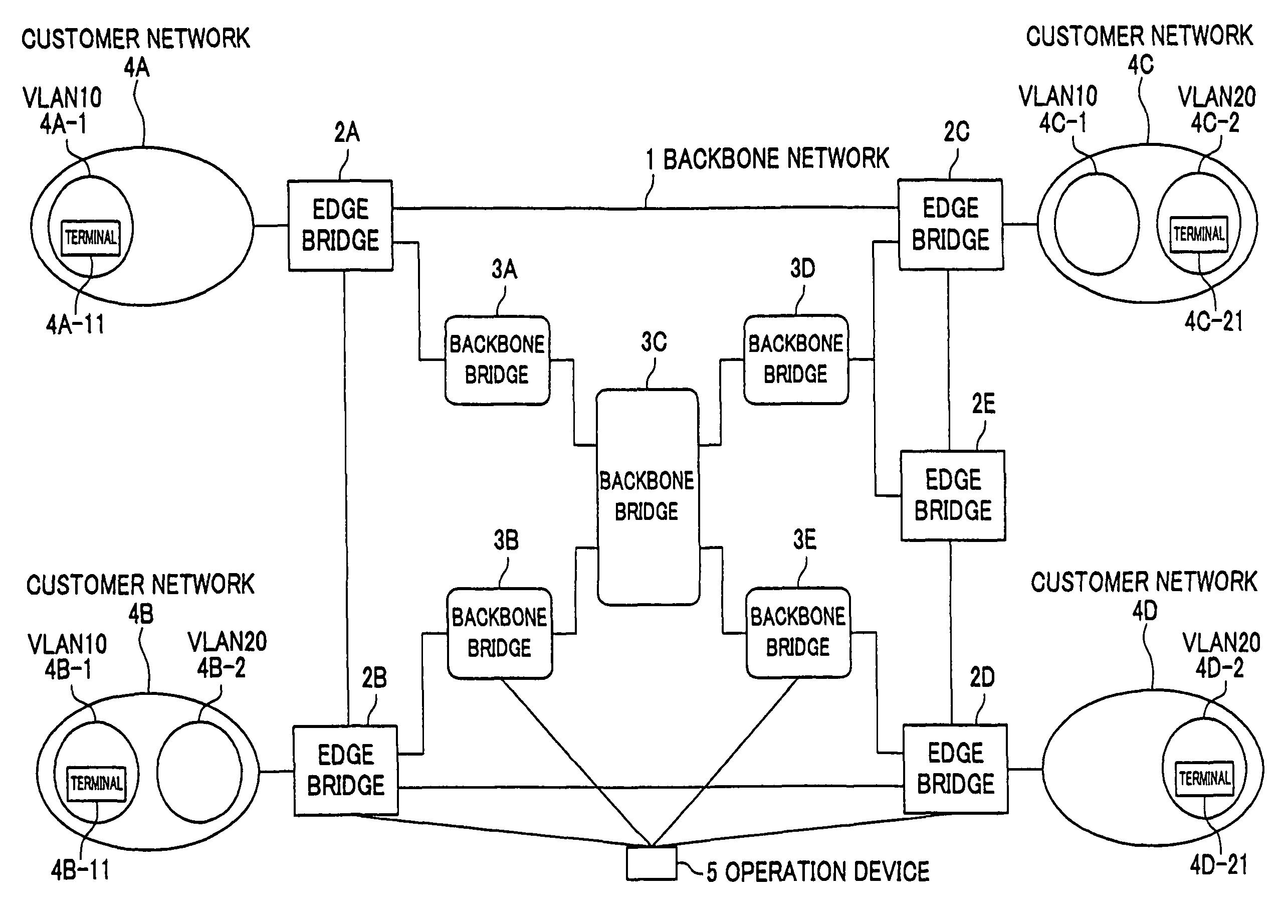
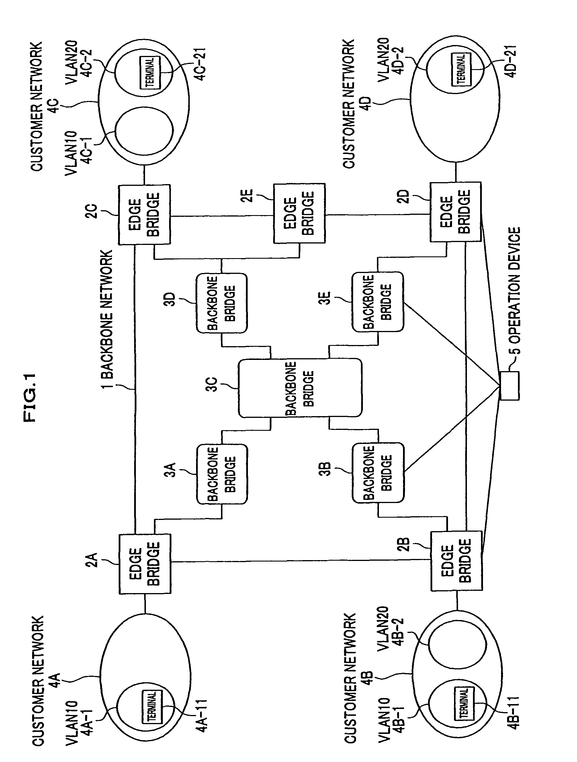
[0064]FIG. 1 is a block diagram showing an exemplary arrangement of a network to which a flooding reduction method according to the first embodiment of the invention is applied. As shown in FIG. 1, a backbone network 1 according to the embodiment comprises a plurality of edge bridges 2A through 2E and a plurality of backbone bridges 3A through 3E. The backbone network 1 is connected with customer 4A via edge bridge 2A, with customer 4B via primary edge bridge 2B, with customer 4C via primary edge bridge 2C, and with customer 4D via edge bridge 2D. Also, an operation device 5 is connected with all edge bridges 2A through 2E and all backbone bridges 3A through 3E of the backbone network 1. Each of th...

second embodiment

=Edge+Core+Ops+B−DA+Multicast Filter

[0084]Referring to FIG. 6, a flooding reduction method as a MAC frame transfer method and a flooding reduction apparatus according to a second embodiment (embodiment 2) of the invention will be described in the following.

[0085]FIG. 6 shows an exemplary arrangement of a network according to the present invention. Detailed description of the same elements as those of the first embodiment shown in FIG. 1 will be omitted. The structures of edge bridges and backbone bridges are identical to those of the first embodiment and accordingly will not be detailed.

[0086]In FIG. 6, to a customer network 4A, there is connected a terminal 4A-31 which receives a multicast group 10. To a customer network 4B, there is connected a terminal 4B-31 which receives a multicast group 10. To a customer network 4C, there is connected a terminal 4C-31 which receives a multicast group 10. To a customer network 4D, there is connected a terminal 4D-31 which does not receive a mu...


PUM


Abstract

In receiving a MAC (media access control) frame whose destination address is any of a broadcast address, an unknown multicast address and an unknown unicast address, the flooding is reduced by broadcasting the received MAC frame to all the other ports than one that has received the MAC frame. An output control that attains this object is realized by using a destination group identifier (ID) look-up table (2-T1) which enables a look-up of a destination group ID by using, as a key, any one or combination of header information of the MAC frame, a port which received the MAC frame and a service VLAN (virtual local area network) ID corresponding to the MAC frame and a backbone port look-up table (2-T2) which enables a look-up of at least one backbone port which is to transmit or at least one backbone port which is not to transmit by using the destination group ID as a key.

Description

[0001]The present invention relates to a method of reducing the flooding of customer frames in a transfer route in a virtual local area network (VLAN) service provided by a provider for customers.BACKGROUND ART[0002]If a bridge receives, in a network provided through bridges, a MAC (media access control) frame whose destination address is a broadcast address, an unknown multicast address or an unknown unicast address, then the bridge broadcasts (or simultaneously sends) the MAC frame to all of the other ports than the port that has received the MAC frame This disadvantageously increase a probability that terminals connected to the network will receive MAC frames unnecessary for the terminals to receive, which causes a problem that links interconnecting the bridges may have their bands compressed due to the unnecessary MAC frames.[0003]Similarly, if a bridge receives a MAC frame which belongs to an unknown VLAN and which has, as the destination address, a broadcast address, an unknow...

Claims


Application Information

Patent Timeline
Patent Type & Authority Patents(United States)
IPC IPC(8): H04L12/28H04L12/56H04L45/74H04L12/46
CPCH04L12/4641H04L12/56H04L45/32
Inventor HATO, KUNIOSUZUKI, MUNEYOSHI
Owner NIPPON TELEGRAPH & TELEPHONE CORP
Why Eureka
Try Eureka