Fuel Cell Cathode and a Polymer Electrolyte Fuel Cell Having the Same

a fuel cell and electrolyte technology, applied in the direction of fuel cells, solid electrolyte fuel cells, cell components, etc., can solve the problems of inability to fully exploit the performance of high oxygen permeability materials, difficult to guide oxygen to locations near the surface of catalysts, and inability to combine simple physical mixtures to allow highly oxygen-permeability polymers to exist near the three-phase interface in a concentrated manner. , to achieve the effect of excellent electrode characteristics, high battery output and superior durability

Inactive Publication Date: 2008-11-13
TOYOTA JIDOSHA KK
View PDF6 Cites 10 Cited by
  • Summary
  • Abstract
  • Description
  • Claims
  • Application Information

AI Technical Summary

Benefits of technology

[0031]By thus utilizing the above-described cathode of the invention that has excellent electrode characteristics with respect to oxygen reducing reactions, a polymer electrolyte fuel cell having high battery output can be provided. Furthermore, as mentioned above, the cathode of the invention is capable of sufficiently preventing flooding and has superior durability, and the polymer electrolyte fuel cell of the invention having the cathode can provide high battery output stably over a long period of time.
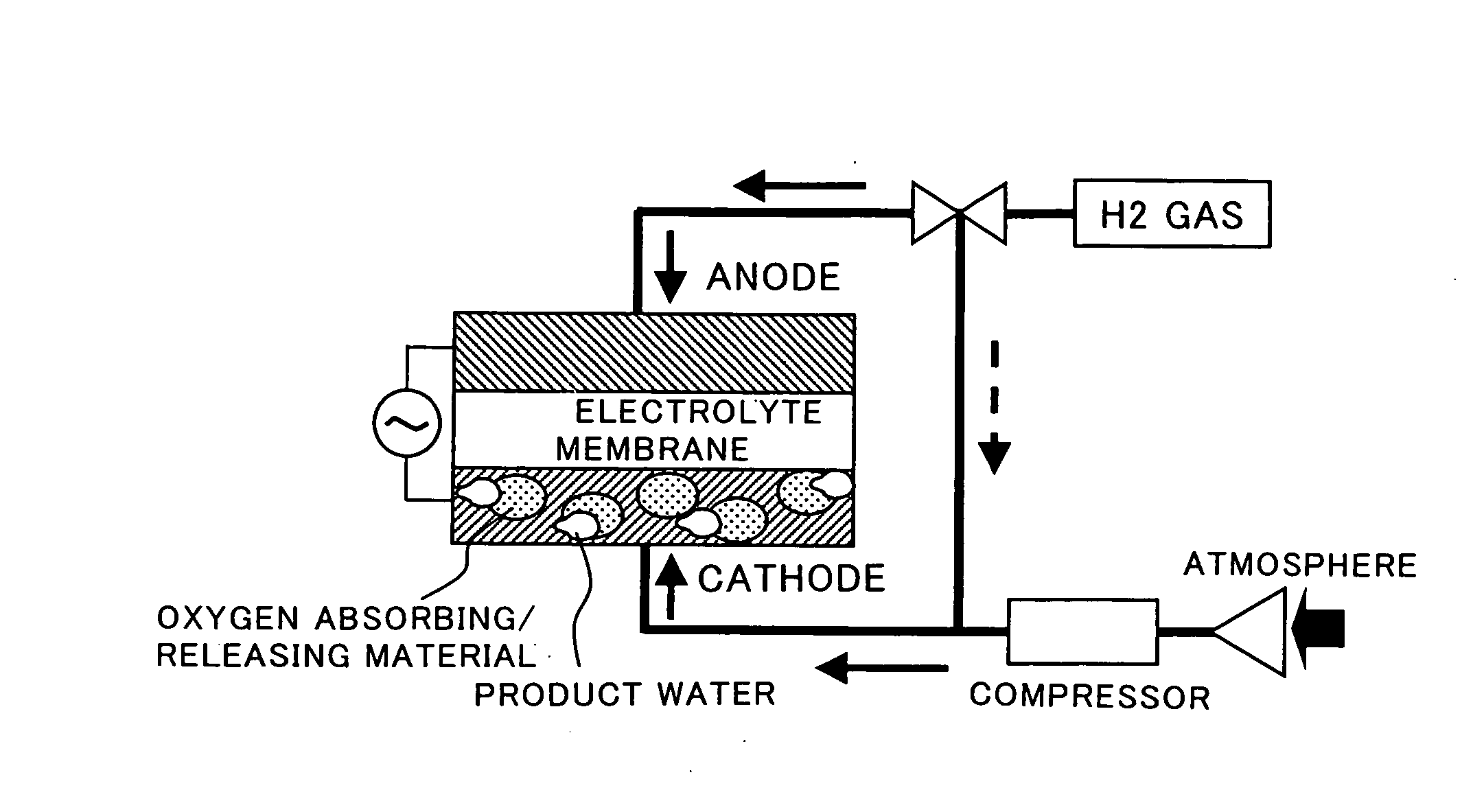
[0032]In a third aspect, the invention provides a method of operating a polymer electrolyte fuel cell comprising an anode, a cathode, and a polymer electrolyte membrane disposed between the anode and the cathode. The cathode comprises the above-described fuel cell cathode. The method comprises feeding hydrogen gas to the oxygen absorbing / releasing material, which is comprised of one or more of CeO2, CeO2—ZrO2, CeO2—ZrO2—Y2O3, CeO2—ZrO2-rare-earth oxide, periodically and in a pulsed manner before or during operation so as to treat CeO2 to be partly reduced to Ce2O3. By thus reducing part of CeO2 to Ce2O3, enhanced battery performance (generation efficiency) can be achieved throughout all current density regions as compared with a case where no reduction process is carried out at regular intervals before and / or during operation.
[0033]In a system whereby hydrogen is circulated in a pulsed manner to the cathode into which the oxygen absorbing / releasing material is mixed, accumulation of product water can be suppressed and flooding can be reduced. As a result, high performance can be provided throughout all current density regions.

Problems solved by technology

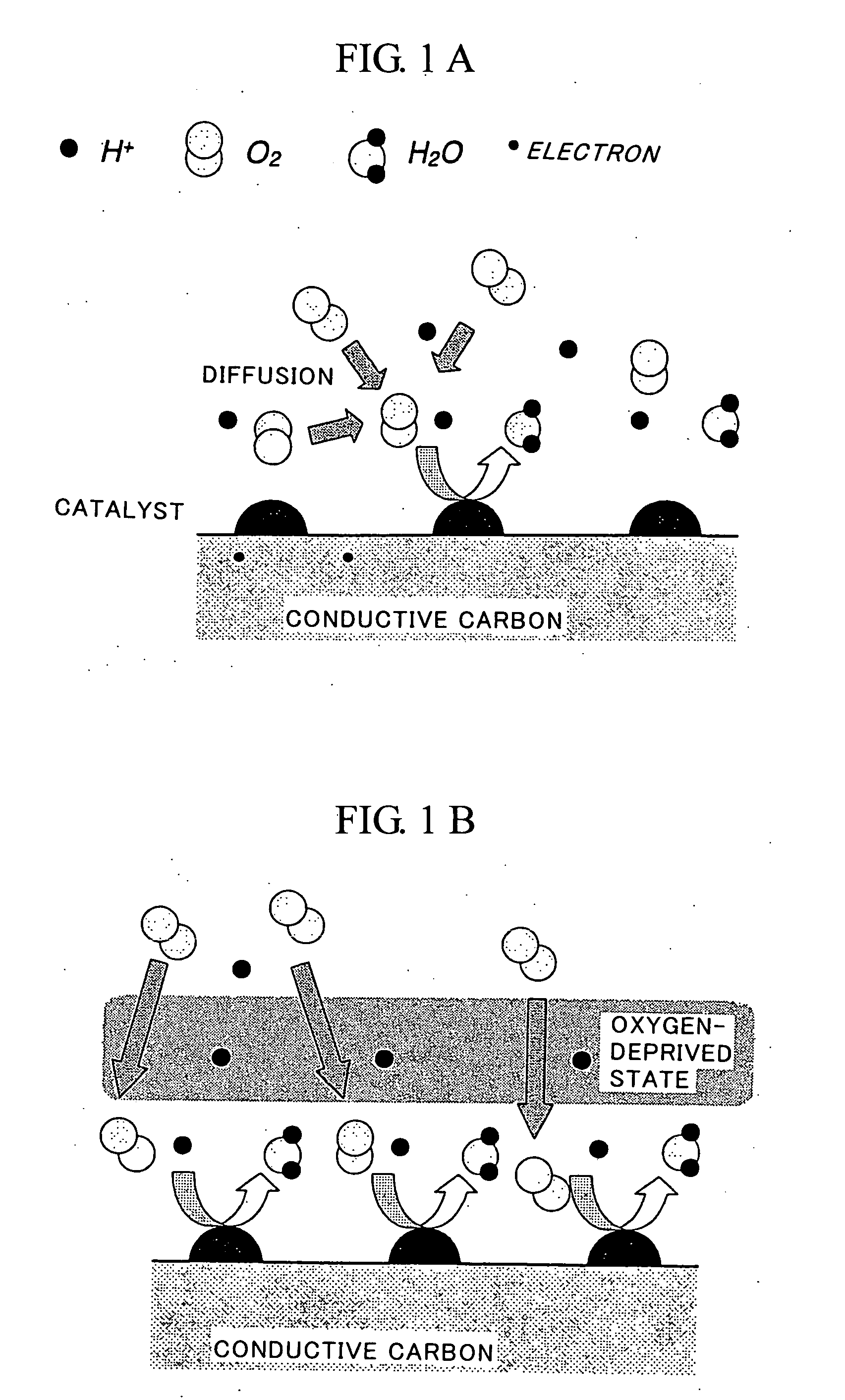
As a result, if the product water increases, it becomes difficult to guide oxygen to locations near the surface of the catalyst.
In other words, the problem is that the product water drainage path and the oxygen diffusion path are located at the same place.
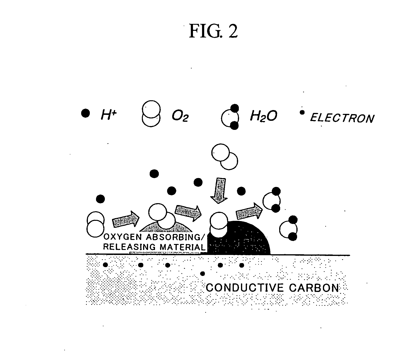
One of important issues is the feeding of oxygen to the three-phase interface.
However, what oxygen actually needs is the three-phase interface, and it is impossible for a simple physical mixture to allow a highly oxygen-permeable polymer to exist near the three-phase interface in a concentrated manner.
The result is that the performance of the high oxygen permeability material cannot be fully exploited.
As a result, the catalytic activity cannot be fully enhanced.

Method used


Image

  • Fuel Cell Cathode and a Polymer Electrolyte Fuel Cell Having the Same
  • Fuel Cell Cathode and a Polymer Electrolyte Fuel Cell Having the Same
  • Fuel Cell Cathode and a Polymer Electrolyte Fuel Cell Having the Same

Examples


example 1

Example 1

[0062]A CeO2—ZrO2 complex oxide was used as an oxygen absorbing / releasing agent. Printex XE2B was used as the carbon material, and for the platinum material, chloroplatinic acid was caused to be supported by the carbon by impregnation. A CeO2—ZrO2 complex oxide (20 wt. %) that supported 5 wt. % of Pt was mixed with the platinum-supported carbon, thereby preparing a catalyst.

example 2

Example 2-1

[0069]An electrode with a membrane thickness of 3 mil comprising a PtFe(60 wt. %)-supported carbon catalyst mixed with a Pt(5 wt. %)-supported Ce—Zr—Ox powder (20 wt. %) was prepared in the following procedure.

[0070](1) A Ce—Zr—Ox complex oxide powder was immersed in an aqueous solution of dinitrodiamine Pt complex, stirred, and then evaporated at 120° C. to dryness (5 wt. % of Pt contained relative to the powder).

[0071](2) After grinding in a mortar, the powder was baked in an atmospheric baking furnace at 500° C. for 2 hours, and the powder was again ground in a mortar.

[0072](3) A commercially available PtFe(60 wt. %)-supported carbon catalyst was mixed with predetermined amounts of ion-exchanged water, a Pt 5 wt. %-supported Ce—Zr—Ox powder (20 wt. % relative to catalyst), an electrolyte solution (Nafion), ethanol, and propylene glycol to obtain a catalyst ink.

[0073](4) After stirring the catalyst ink using an ultrasound homogenizer for 30 minutes, stirring was carried...

example 2-2

[0077]An electrode with a membrane thickness of 6 mil comprising a PtFe(30 wt. %)-supported carbon catalyst mixed with a Pt(5 wt. %)-supported Ce—Zr—Ox powder (20 wt. %) was prepared. This example is similar to Example 2-1 except for the substitution of a PtFe(30 wt. %)-supported carbon catalyst in step (3) and for the use of a membrane thickness of 6 mil in step (5).


PUM

PropertyMeasurementUnit
particle sizeaaaaaaaaaa

Abstract

A fuel cell cathode comprises a catalyst layer comprised of a catalyst-supported electrically conducive carrier and a polymer electrolyte. The catalyst-supporting electrically conductive carrier further supports or has mixed therein a catalyst that is in contact with an oxygen absorbing/releasing material. The cathode has excellent electrode characteristics with respect to oxygen-reducing reactions. A polymer electrolyte fuel cell fitted with the cathode can provide high battery output.

Description

TECHNICAL FIELD[0001]The present invention relates to a fuel cell cathode and a polymer electrolyte fuel cell having such fuel cell cathode.BACKGROUND ART[0002]Polymer electrolyte fuel cells having a polymer electrolyte membrane can be easily reduced in size and weight. For this reason, there is a growing expectation for the practical application thereof as a power source for moving vehicles, such as electric vehicles, and for small-sized cogeneration systems. However, polymer electrolyte fuel cells have relatively low operation temperatures, and it is difficult to effectively utilize the resultant exhaust heat for auxiliary mobile power purposes or the like. Therefore, if the polymer electrolyte fuel cell is to be put to practical use, capabilities must be provided for obtaining high generation efficiency and high output density under operation conditions with high anode reaction gas (such as pure hydrogen, for example) and cathode gas (such as air, for example) utilization ratios....

Claims


Application Information

Patent Timeline
Patent Type & Authority Applications(United States)
IPC IPC(8): H01M8/00H01M8/10H01M4/86H01M4/88H01M4/90H01M4/92
CPCH01M4/8605H01M4/8828H01M4/90H01M4/921H01M4/926H01M8/1004Y02E60/521Y02E60/50
Inventor KAWAMURA, TETSUO
Owner TOYOTA JIDOSHA KK
Why Eureka
Try Eureka