Motor vehicle with knee airbag

a knee airbag and motor vehicle technology, applied in the direction of vehicle components, pedestrian/occupant safety arrangements, vehicular safety arrangments, etc., can solve the problem of sideways retention of knees, and achieve the effect of improving the desired contouring effect and good shape stability

Inactive Publication Date: 2010-07-20
AUTOLIV DEV AB
View PDF17 Cites 4 Cited by
  • Summary
  • Abstract
  • Description
  • Claims
  • Application Information

AI Technical Summary

Benefits of technology

[0005]Starting from this point, the task of the invention is to further develop a motor vehicle with at least one knee airbag in such a way that, using simple means, improved protection of the occupant in case of a laterally-offset frontal impact is achieved.
[0006]In most motor vehicles, the footwell assigned to the vehicle occupant sitting at the front, in other words the area of the vehicle in front of the front seat, is limited on the one side by the inner structure of the vehicle and on the other side by a centre console. According to the invention, the knee airbag is now formed in such a way that its width, if it could expand unhindered, would be greater than the space available to it between vehicle inner structure, for example the driver / passenger door, and the centre console. The superfluous volume of the knee airbag therefore escapes to the inside, so that bolster-shaped areas form on the sides, which leads to sideways retention of the knees. The inflated knee airbag is therefore contoured, without the need for complicated shaping of the airbag cover. The desired contouring effect can be improved still further by use of capture tapes running through the airbag.
[0007]Because the bolster-shaped areas are supported on the vehicle inner structure and the centre console, very good shape stability results. The knee airbag cannot escape, so that there are superb retention effects in case of force influence which goes crossways to the front through the knee-shin area of the occupants.
[0008]The fact that the knee airbag is wedged in also prevents a knee from striking through between the airbag and a side structural barrier.

Problems solved by technology

The superfluous volume of the knee airbag therefore escapes to the inside, so that bolster-shaped areas form on the sides, which leads to sideways retention of the knees.

Method used


Image

  • Motor vehicle with knee airbag
  • Motor vehicle with knee airbag
  • Motor vehicle with knee airbag

Examples


Embodiment Construction

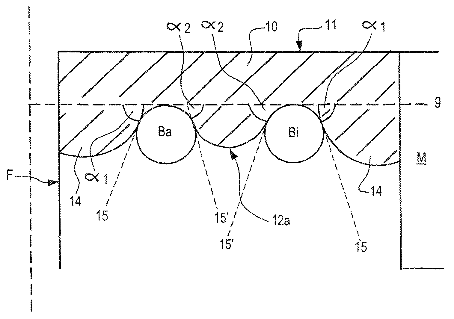
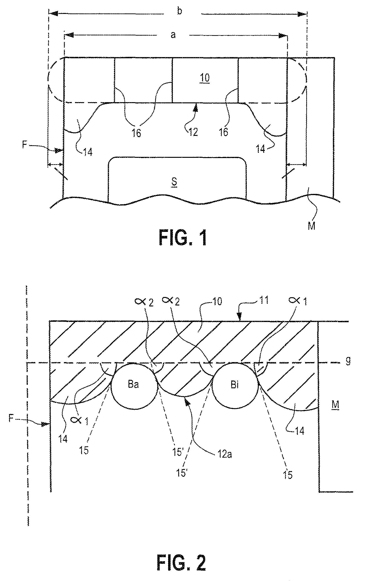
[0014]FIG. 1 shows a schematic view of a part of a front seat S and the footwell in front of it with a knee airbag 10 in a horizontal section. Knee airbag 10, inflated by a gas generator which is not shown, is fully expanded. As can be seen, knee airbag 10 forms bolster-shaped areas 14 on its sides. These bolster-shaped areas occur because the maximum width b, which the knee airbag 10 would have, if it could unfold freely, is bigger than the space available to it between vehicle inner structure F and inner side of centre console M. The shape which knee airbag 10 would have if it could unfold freely, is shown by a dotted line. Preferably, width b of the knee airbag is 30 to 100 mm larger than separation a which is available.

[0015]The bolster-shaped areas 14 which form mean that the occupant is better supported if he or she moves crossways, which on the one hand prevents contact of the knees with the centre console or the vehicle inner structure, and sideways slipping through between ...


PUM


Abstract

A knee airbag is described which is located in front of a front seat (S) in the footwell, whereby this footwell is limited on a first side by the vehicle inner structure (F) and on the side lying opposite the first side is limited by a center console (M). When it is completely filled and free from external forces, this knee airbag (10) exhibits a certain maximum width (b) horizontally and perpendicularly to the longitudinal axis of the motor vehicle (f). In order to improve the safety of the vehicle occupants in case of a laterally-offset frontal collision, knee airbag (10) is arranged in the footwell in such a way that its maximum width (b) in inflated state is greater than the separation (a) between vehicle inner structure (F) and center console (M).

Description

TECHNICAL AREA OF THE INVENTION[0001]The invention relates to a motor vehicle with at least one knee airbag.[0002]Use of knee airbags in motor vehicles is known. Such knee airbags serve, together with a driver or passenger airbag and a seat belt system, to protect the vehicle occupants in case of a frontal collision or a laterally-offset frontal collision. In such a case, the knee airbag has two main tasks: on the one hand it should prevent the knee-shin area of the occupant from striking the inner structure of the vehicle. Furthermore, a knee airbag has the task of holding the occupant in his or her seating position in case of a frontal impact. This task is normally shared with the seat belt system; the knee airbag should, however, ideally be designed in such a way that it succeeds in holding the occupant in position—at least to a limited extent—even if the seat belt is not being worn.STATE OF THE ART[0003]Knee airbags which have existed up to now are primarily designed in order to...

Claims


Application Information

Patent Timeline
Patent Type & Authority Patents(United States)
IPC IPC(8): B60R21/16B60R21/231B60R21/00B60R21/233B60R21/2338
CPCB60R21/231B60R2021/0004B60R2021/0009B60R2021/23169B60R2021/23382B60R21/206B60R21/205B60R21/045
Inventor NARIN, MUHAMMED ALIGRUBER, ARNO
Owner AUTOLIV DEV AB
Why Eureka
Try Eureka