
Loading space cover

a technology for space covers and loading, applied in the direction of roofs, curtain suspension devices, transportation items, etc., can solve the problems of loading space covers rotating loading space covers twisting about their longitudinal axes, and loading or the drinks crates are jammed simultaneously under the loading space covers, etc., to achieve small loading space, simple design, and cost-effective design

Active Publication Date: 2010-08-05
DR ING H C F PORSCHE AG
View PDF12 Cites 1 Cited by
  • Summary
  • Abstract
  • Description
  • Claims
  • Application Information

AI Technical Summary

Benefits of technology

The invention is a loading space cover for a motor vehicle that can rotate in case of an accident. The cover is designed to protect the load from sliding forward during a crash. The cover has fastening devices that engage with the fasteners in the loading space. The fastening devices are simple and cost-effective. The cover is fixed to the fasteners in the loading space, and the load pushes forward and gets jammed in three sides: from above by the cover, from the front by the rear seat backrests, and from below by the floor of the loading space. This improves occupant protection in a motor vehicle. The fastening devices have a locking mechanism that can be unlocked and adjusted in the longitudinal direction of the cover. The entire fastening device has a simple design and can be produced with low storage and logistical costs. The invention is also cost-effective for the mid-range price sector.

Problems solved by technology

Thus, a load that slides forward during an accident or other sudden deceleration will cause the loading space cover to rotate about its longitudinal axis.
The load continues to push forward if the deceleration during the crash is too great, and will cause the loading space cover to twist about its longitudinal axis.
As a result, the load or the drinks crates are jammed simultaneously under the loading space cover.
Further deceleration causes the load to abut against a rear side of the rear seat backrest.
As a result, the load is jammed in at three sides, specifically from above by the loading space cover, from the front by the rear side of the rear seat backrest, and from below by a floor of the loading space.
As a result, the fastening device generally makes do with a small number of parts and can be produced with expedient storage and logistical costs for the individual components.

Method used


Image

  • Loading space cover
  • Loading space cover
  • Loading space cover

Examples


Embodiment Construction

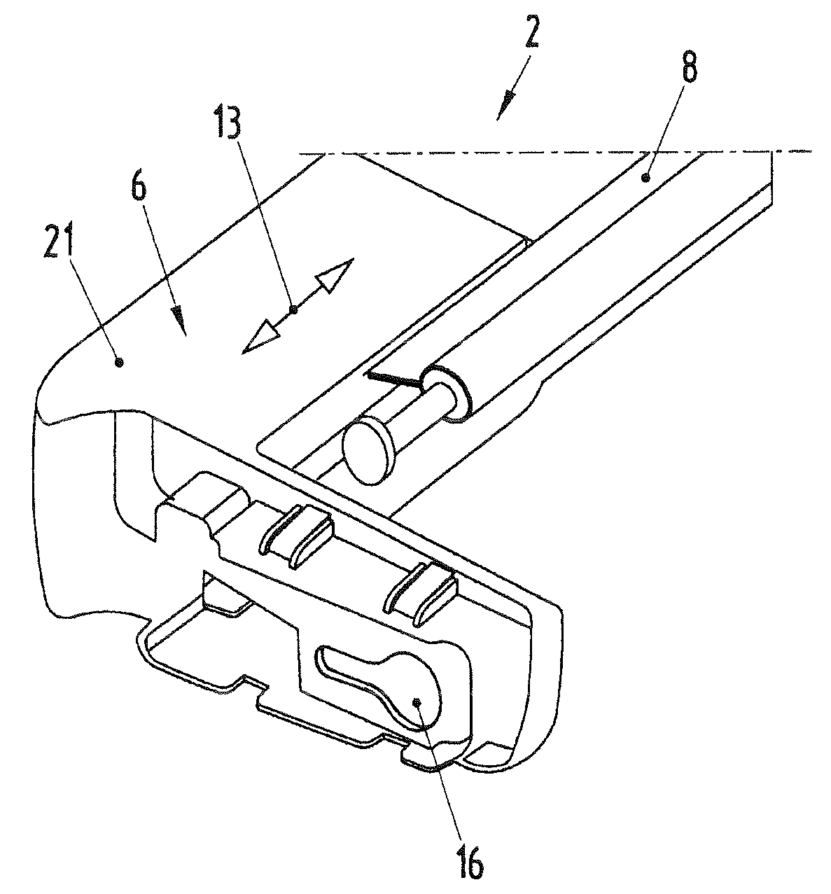
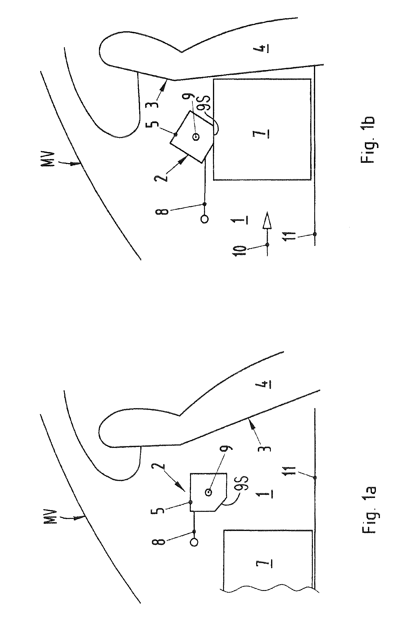
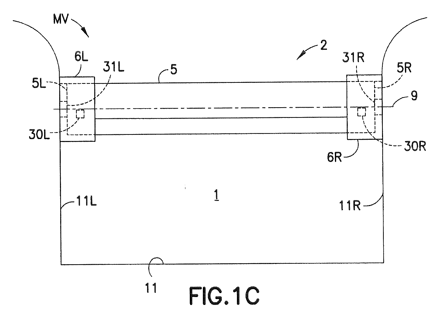
[0020]A loading space of a motor vehicle MV is identified generally by the numeral 1 in FIGS. 1a and 1b. The loading space 1 is defined partly by a loading space floor 11 and opposite left and right sides 11L and 11R, as shown in FIG. 1c. The loading space 1 has a loading space cover 2, which is shown at a distance from a rear side 3 of a backrest 4 of a passenger seat of the motor vehicle MV. However, the loading space cover 2 can directly adjoin the rear side 3 of the rear seat backrest 4. The loading space cover 2 has a dimensionally stable housing 5 with opposite longitudinal ends 5L and 5R spaced from one another in the transverse direction of the vehicle and hence near the left and right sides of the motor vehicle MV. Fastening devices 6L and 6R are arranged at the longitudinal ends 5L, 5R of the housing 5 of the loading space cover 2, as shown in FIGS. 1c and 2 to 4 and can be moved selectively toward and away from each other between retracted positions where the spacing betw...


PUM


Abstract

A loading space cover having a dimensionally stable housing and a flexible sheet like screen is rolled up in the housing. Fastening devices are disposed at the longitudinal end sides of the loading space cover. Each fastening device can be held releasably in associated loading-space fasteners of a motor vehicle. The fastening devices are of structurally simple and cost-effective design. Additionally, in the event of a crash, the fastening devices are held reliably in the loading-space fasteners and permit an energy-absorbing twisting of the loading space cover about its longitudinal axis.

Description

CROSS-REFERENCE TO RELATED APPLICATIONS[0001]This application claims priority under 35 USC 119 to German Patent Application No. 10 2009 006 876.7 filed on Jan. 30, 2009, the entire disclosure of which is incorporated herein by reference.BACKGROUND OF THE INVENTION[0002]1. Field of the Invention[0003]The invention relates to a loading space cover having a dimensionally stable housing in which a flexible sheetlike structure, such as a screen, is mounted so that it can be rolled up. The invention also relates to a motor vehicle fitted with a loading space cover of this type.[0004]2. Description of the Related Art[0005]DE 20 2006 018 470 U1 discloses a generic loading space cover for a motor vehicle. The loading space cover has a flexible sheetlike structure for restraining a load and a dimensionally stable housing unit that is held releasably in loading-space-side fasteners. Means are provided for moving the housing unit into a securing position, in which the housing unit is in positiv...

Claims


Application Information

Patent Timeline
Patent Type & Authority Applications(United States)
IPC IPC(8): B60R5/04E05C5/00B60R11/00
CPCB60R5/047Y10T292/0806
Inventor KRUGER, MATHIAS
Owner DR ING H C F PORSCHE AG
Learn More