Valve pistol for a high-pressure cleaning device

A high-pressure cleaning and valve gun technology, applied in the direction of liquid cleaning methods, cleaning methods and utensils, chemical instruments and methods, etc., can solve the problems of unfavorable roughness, damage to the sealing ring, damage to the sealing ring, etc., and achieve low cost, Avoid Gap Squeeze Effects

Active Publication Date: 2018-12-21
ALFRED KARCHER GMBH & CO KG
View PDF7 Cites 0 Cited by
  • Summary
  • Abstract
  • Description
  • Claims
  • Application Information

AI Technical Summary

Problems solved by technology

The increased roughness adversely affects the sealing effect that the sealing ring can achieve, and since the valve tappet performs a movement relative to the sealing ring, lime particles deposited on the valve tappet can damage the sealing ring
Corresponding damage to the sealing ring can also be caused by other abrasive particles carried by the cleaning fluid, such as rust particles, and the sealing effect of the sealing ring can be adversely affected

Method used


Image

  • Valve pistol for a high-pressure cleaning device
  • Valve pistol for a high-pressure cleaning device
  • Valve pistol for a high-pressure cleaning device

Examples


Embodiment Construction

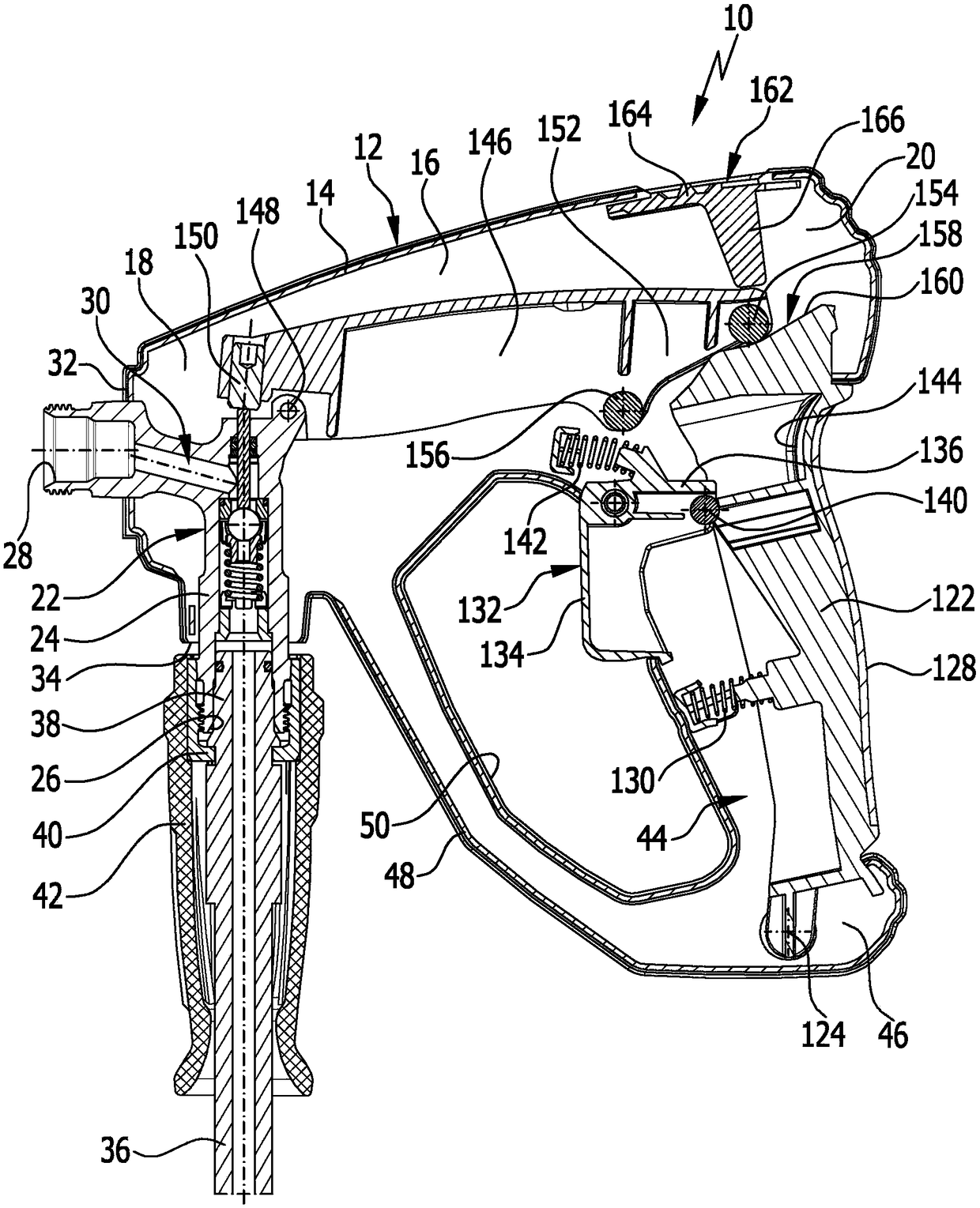
[0036] exist figure 1 An advantageous embodiment of the valve gun according to the invention is schematically shown in FIG. 1 and is generally assigned the reference numeral 10 . The valve gun 10 comprises a gun housing 12 which is formed in a conventional manner from a first housing half 14 and a second housing half, not shown in the figures. The gun housing 12 has a central housing area 16 which is arranged between a front housing area 18 and a rear housing area 20 .

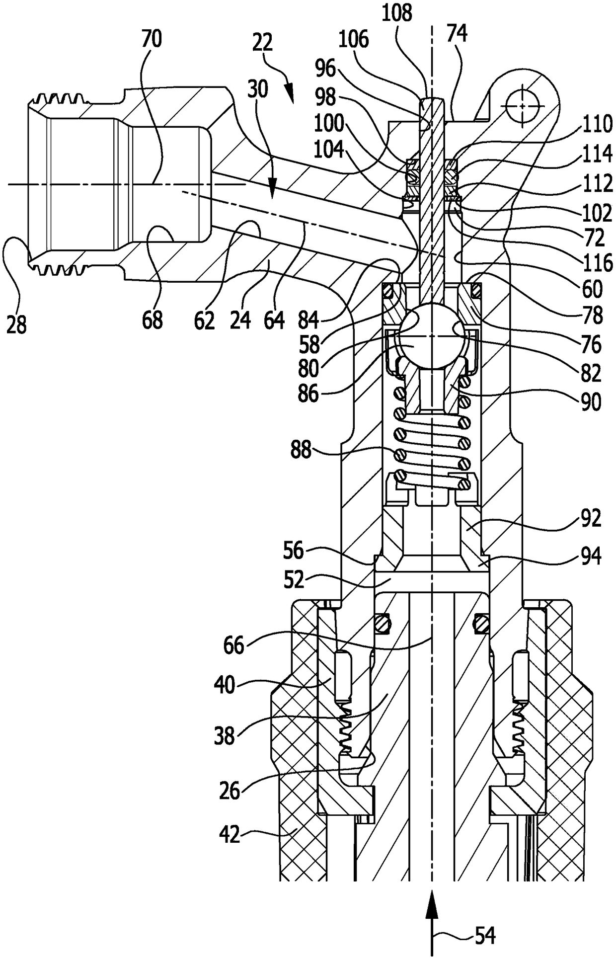
[0037] The front housing region 18 accommodates a valve 22 which has a valve housing 24 . The valve housing 24 has an inlet 26 and an outlet 28 which are in flow connection with one another via a through-channel 30 . In the embodiment shown, the outlet 28 protrudes from the front side 32 of the gun housing 12 . A nozzle can, for example, be connected to the outlet 28 . In the embodiment shown, the inlet 26 protrudes from the underside 34 of the gun housing 12 . In the embodiment shown, a pressure hose 36 ...


PUM


Abstract

The invention relates to a valve pistol for a high-pressure cleaning device, having a valve (22) which has a valve housing (24) with a passage duct (30), which passage duct has a first duct section (52) in which there are arranged a valve seat (82) and a closing body (86) which, in a closed position, bears against the valve seat (82), wherein the closing body (76) is movable into an open positionby displacement of a valve plunger (106), and the valve plunger (106), surrounded by a sealing ring (114), extends through a plunger duct (72) which opens into the first duct section (52), and, outside the valve housing (84), said valve plunger is mechanically coupled to a release lever (122). To further develop the valve pistol (10) such that the risk of an impairment of the sealing action of thesealing ring (114), and damage to the sealing ring (114), is reduced, it is proposed that the valve plunger (106) be surrounded by a stripper ring (110, 112) which is arranged adjacent to the sealingring (114) and which bears against the valve plunger (106) and which is held together with the sealing ring (114) in the plunger duct (72) by a holding element (116) which is arranged with a spacingto the valve seat (82).

Description

technical field [0001] The invention relates to a valve lance for a high-pressure cleaning device, the valve lance has a valve, the valve has a valve housing, the valve housing has a through channel extending from an inlet to an outlet, the through channel has a first channel section, in which Arranged in a channel section are the valve seat and the closing body which bears against the valve seat in the closed position under the action of the closing spring, wherein the closing body can be moved by pushing the valve tappet into a position spaced apart from the valve seat. In the open position, and surrounded by a sealing ring, the valve tappet extends through the tappet channel in the first channel section and is mechanically coupled outside the valve housing to the trigger lever, which is pivotable about the pivot axis. Background technique [0002] With the aid of such a valve gun, the discharge of cleaning fluid pressurized by the high-pressure cleaning device can be cont...

Claims


Application Information

Patent Timeline
Patent Type & Authority Applications(China)
IPC IPC(8): B05B1/30B05B9/01B05B12/00B08B3/02B05B15/14
CPCB05B1/302B05B9/01B05B12/002B08B3/028B05B15/14B05B12/0026
Inventor 马丁·埃费尔贝恩德·罗梅尔
Owner ALFRED KARCHER GMBH & CO KG
Why Eureka
Try Eureka