Sealing method and sealing system for pipes in closed walls

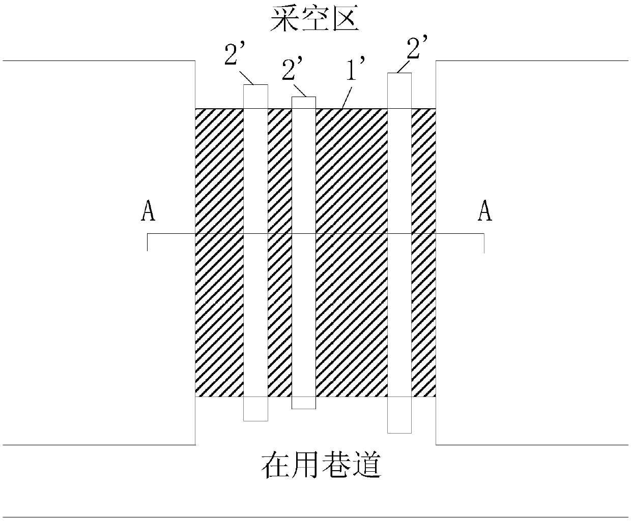
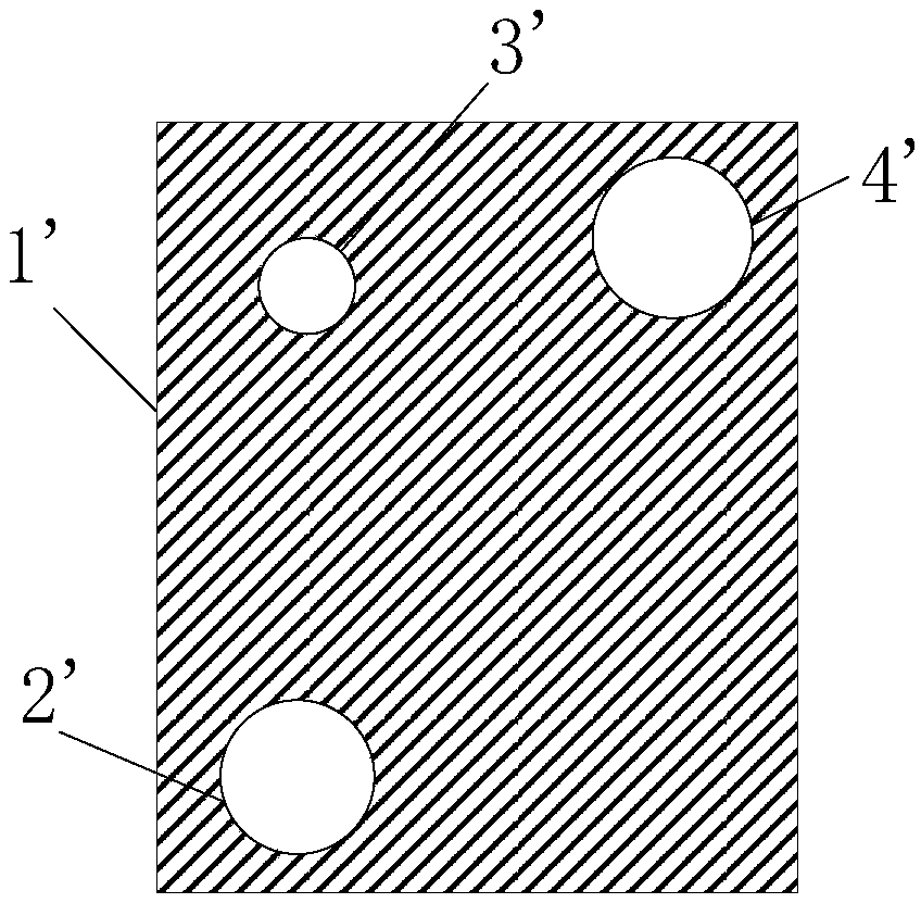
A closed system and closed wall technology, applied in the direction of pipes, pipes/pipe joints/fittings, mechanical equipment, etc., can solve the problem of damaging the sealing effect of the closed wall 1', serious air leakage at the connection between the pipe 2' and the gate valve, and affecting the closed wall 1'Sealing effect and other issues

Active Publication Date: 2019-04-05
CHINA SHENHUA ENERGY CO LTD +1
View PDF6 Cites 0 Cited by
  • Summary
  • Abstract
  • Description
  • Claims
  • Application Information

AI Technical Summary

Problems solved by technology

But the sealing effect is not ideal
The gasket of the gate valve is prone to aging, and the plugging effect of the butter is not ideal, resulting in more serious air leakage at the connection between the pipe 2' and the gate valve
When the top of the airtight wall 1' is subjected to greater pressure, the contact surface of the pipe 2' near the top and the airtight wall 1' will be subject to a greater extrusion force, resulting in cracks in the wall that may even expand into air leakage channels. Destroy the sealing effect of the airtight wall 1'
[0005] In addition, the pipeline 2' is pressure-set inside the airtight wall 1', and it is difficult to completely seal the contact surface between the pipeline 2' and the airtight wall 1'. An air leakage channel surrounding the straight pipe is formed between the outside and the airtight wall 1', which further affects the sealing effect of the airtight wall 1'

Method used


Image

  • Sealing method and sealing system for pipes in closed walls
  • Sealing method and sealing system for pipes in closed walls
  • Sealing method and sealing system for pipes in closed walls

Examples


Embodiment Construction

[0040] In order to make the purpose, technical solutions and advantages of the present invention clearer, the present invention will be described in further detail below in conjunction with specific embodiments and with reference to the accompanying drawings. Wherein the same components are denoted by the same reference numerals. It should be noted that the words "front", "rear", "left", "right", "upper" and "lower" used in the following description refer to directions in the drawings. The terms "inner" and "outer" are used to refer to directions toward and away from, respectively, the geometric center of a particular component.

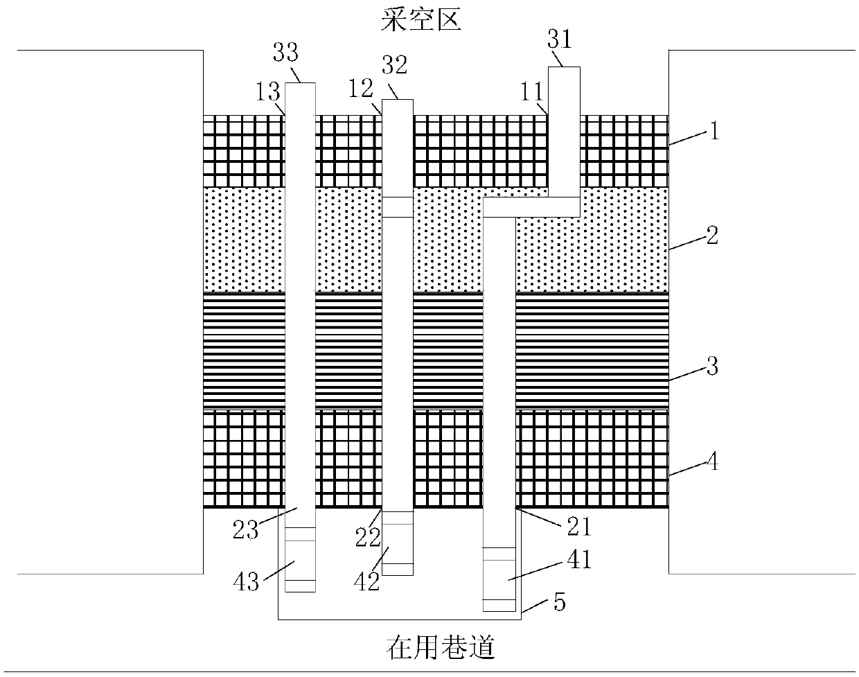
[0041] The sealing method for the pipeline of the airtight wall at least includes the following steps:

[0042] The first step is in the inner wall 1 of the airtight wall (such as image 3 As shown), the inlet holes (such as the first inlet hole 11, the second inlet hole 12, and the third inlet hole 13) are set, and the inner wall 1 is the wall bod...


PUM


Abstract

The invention discloses a sealing method of a pipe for a closed wall and a closing system. The sealing method comprises the following steps: (1) an inlet hole is formed in an inner wall of the closed wall; an outlet hole is formed in an outer wall of the closed wall; and the inlet hole is higher than the outlet hole; (2) a channel is formed between the inner wall and the outer wall, and is communicated with the inlet hole and the outlet hole; (3) the pipe is mounted in the channel; and two ends of the pipe respectively extend to the external of the closed wall from the inlet hole and the outlet hole; and (4) the end part of the pipe for extending out from the outlet hole is connected with a water storage pipe; and water is injected in the water storage pipe for water sealing of the pipe. The sealing method of the pipe for the closed wall and the closing system can provide excellent tightness to the pipe; and the shape of the pipe and the position in the closed wall are changed according to the positions of the inlet hole and the outlet hole, so that the closed wall can realize excellent tightness.

Description

technical field [0001] The present invention relates to downhole airtight wall, more particularly, relate to a kind of sealing method and airtight system for the pipeline of airtight wall. Background technique [0002] In the process of coal mining, in order to isolate the goaf from the working roadway, construction personnel need to build a closed wall in the roadway or roadway connected with the goaf. The airtight wall has the function of isolation and sealing, and the airtight wall can prevent the poisonous gas in the goaf from entering the working roadway. [0003] figure 1 It is a schematic diagram of pipeline installation of an underground closed wall in the prior art. figure 2 for figure 1 The A-A sectional schematic diagram of the downhole sealing wall shown in . Such as figure 1 and figure 2 As shown, the airtight wall 1' can isolate the goaf and the working roadway, and various pipelines 2' are installed on the airtight wall 1'. The pipeline 2' is made of ...

Claims


Application Information

Patent Timeline
Patent Type & Authority Patents(China)
IPC IPC(8): F16L5/02
CPCF16L5/02
Inventor 张立辉秦清河苏志伟
Owner CHINA SHENHUA ENERGY CO LTD
Why Eureka
Try Eureka