
Image processing apparatus, image processing method, and a computer-readable storage medium containing a computer program for image processing recorded thereon

a computer program and image processing technology, applied in the field of image processing apparatus and image processing method, can solve the problems of not being able to make concurrently, the degree of change of the image cannot be grasped immediately, and the work is rather disadvantageous for beginners, so as to achieve convenient and efficient editing and processing of images, improve work efficiency, and optimize magnification

Inactive Publication Date: 2010-07-27
RICOH KK
View PDF18 Cites 14 Cited by
  • Summary
  • Abstract
  • Description
  • Claims
  • Application Information

AI Technical Summary

Benefits of technology

[0014]It is an object of the present invention to provide an apparatus and a method for easily and efficiently editing and processing an image and making it possible even for beginners to easily obtain a contracted image with an optimal magnification for each edited and processed image when contracted images for retrieval are prepared by using images obtained by editing and processing the original images by easily and efficiently changing desired parameter values of a plurality of images and also by changing a color as an object for the processing for making transparent when a blank section is colored with the color as an object for making transparent when an edited and processed image is stored, and also to a computer-readable storage medium containing a computer program for image processing recorded thereon.
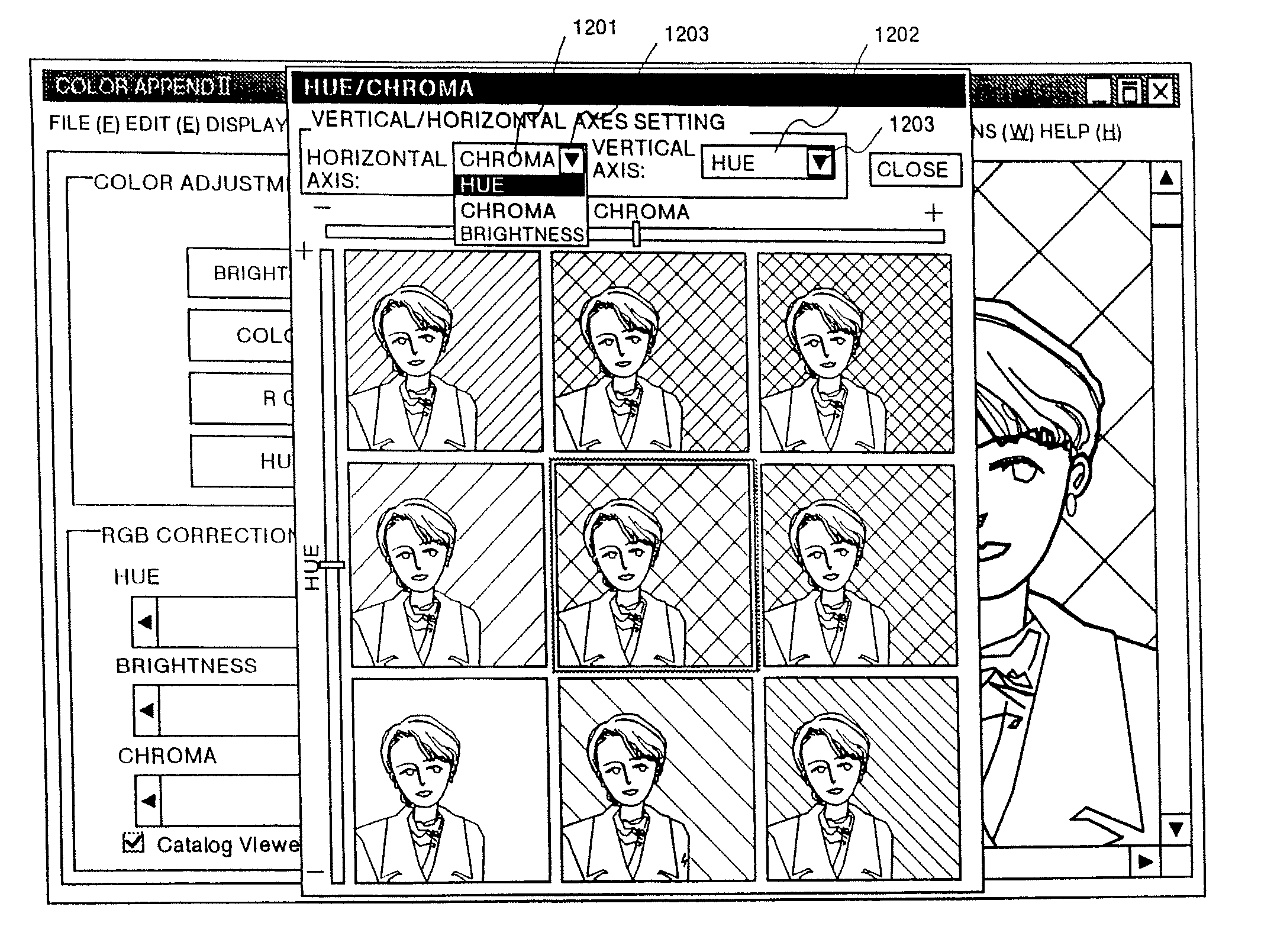
[0015]With the present invention, a reference image is displayed at a specified position on a screen and a peripheral image is displayed around this reference image in n layers by correlating parameters of the peripheral image to scales of the vertical axis and horizontal axis. Thus, parameters of the reference image can be changed by visually checking the peripheral image. More specifically, a peripheral image is located adjacent to the reference image in correlation to scales of the vertical axis and horizontal axis. Thus, an operator can easily recognize synthesis of amount of change of two parameters and change of an image according to the synthesized parameters. Thus, the operator can quickly and efficiently change a plurality of parameters for the reference image.
[0016]With the present invention, it is inhibited that the same parameter is selected as a parameter for both the vertical and horizontal axes simultaneously, so that it is possible to prevent an operator from setting the same parameter for both the vertical axis and horizontal axis by mistake.

Problems solved by technology

In the first type of conventional technology described above, however, each time the parameter values are changed an image displayed on a screen changes so that comparison of the images before and after the change can not be made concurrently and a degree of change of the image can not be grasped immediately.
Persons experienced in this kind of job for editing and processing an image can easily carry out this work, but the work is rather disadvantageously difficult for beginners.
Further, in the first type of conventional technology as described above, when there are a plurality of parameters, the parameter values are required to be changed one by one, and when it is desired to obtain desired parameter values by finely adjusting a change rate of each of two or more discrete parameter values, it is required to check the image each time, and this work is easy for experienced persons, but is difficult for those who are not experienced.
Therefore, for instance, when a rectangular image is rotated, a portion of the image goes out of the frame of the contracted image and the entire image rotated as described above can not be displayed, which makes it impossible to fully grasp the rotated state of the image.
Further, in the second conventional technology, when a portion of an original image is separated in a specified form like in a case where only a section corresponding to a face is separated from a photograph showing the whole body, the separated section is contracted with the same contraction ratio, so that the separated image is shown with a small size in the contracted image, and in some situations the contents of an original image can not fully be grasped from the contracted image.
Further, in the second type of conventional technology, a color as an object for making transparent can not be changed, and when there is the same color as that to be made transparent in may places, not only the blank section, but also sections having the same color as that to be made transparent are disadvantageously made transparent.

Method used


Image

  • Image processing apparatus, image processing method, and a computer-readable storage medium containing a computer program for image processing recorded thereon
  • Image processing apparatus, image processing method, and a computer-readable storage medium containing a computer program for image processing recorded thereon
  • Image processing apparatus, image processing method, and a computer-readable storage medium containing a computer program for image processing recorded thereon

Examples


embodiment 1

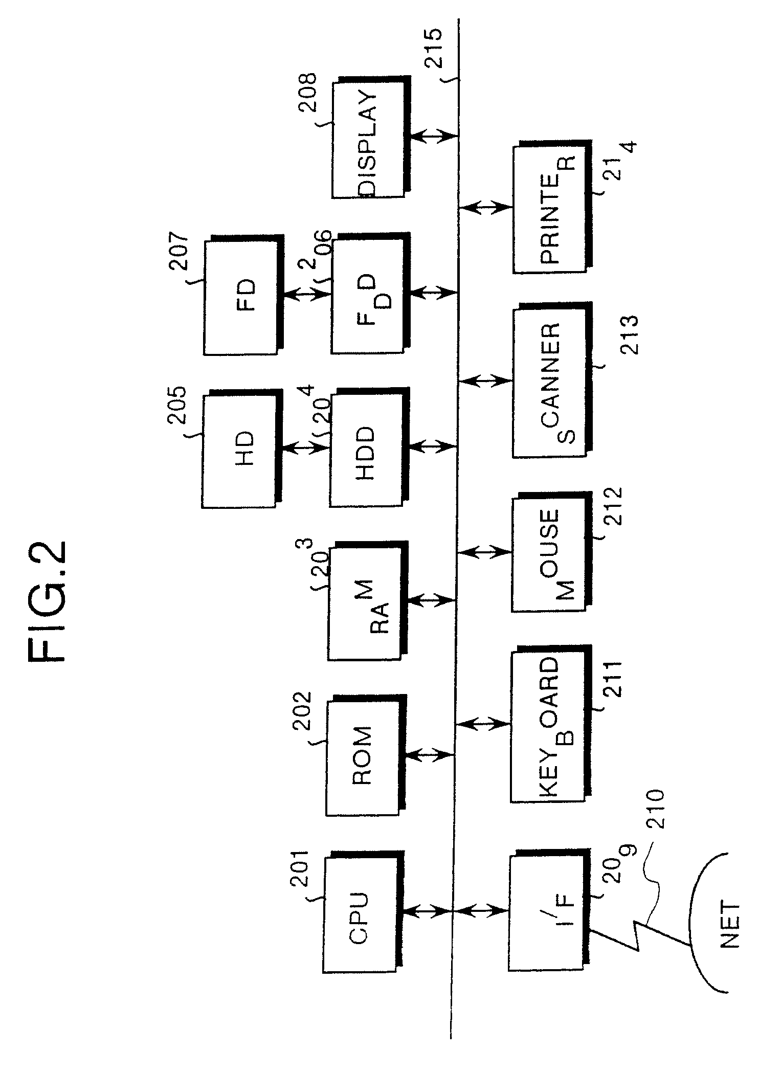
[0104]Hardware configuration of the image processing apparatus 100 is described. FIG. 2 is a block diagram showing hardware configuration of the image processing apparatus of the present invention. In FIG. 2, designated at the reference numeral 201 is a CPU controlling the entire system, at 202 a ROM with a boot program or the like stored thereon, at 203 a RAM used as a work area for the CPU, at 204 a HDD (Hard Disk Drive) for controlling data read / write to and from a HD (hard Disk) 205 under controls by the CPU 201, and at 205 a HD for storing data written thereon according to controls by the HDD 204.

[0105]Further, designated at the reference numeral 206 is a FDD (Floppy Disk Drive) for controlling data read / write to and from a FD (Floppy Disk) according to controls by the CPU 201, at 207 a FD freely set or removed for storing data written under controls by the FDD 206, and at 208 a display for displaying documents each including images or the like and other functional information...

embodiment 2

[0182]Next, description is made for setting of scales for the vertical axis and the horizontal axis. FIG. 12 shows an example of a screen displayed on the display 308 of the image processing apparatus of the present invention. In FIG. 12, a parameter concerning current chroma is set in a horizontal-axis parameter setting frame 1201, and a parameter concerning hue is set in a vertical-axis parameter setting frame 1202.

[0183]By pressing a button 1203 at the right edge of the horizontal-axis parameter setting frame 1201, selectable candidates are displayed as a pull-down menu. It can be seen that hue and brightness including the currently set chroma are displayed thereon as selectable parameter candidates. As for the vertical-axis parameter setting frame 1202, similarly to the horizontal-axis parameter setting frame 1201, by pressing a button 1203 at the right edge thereof, hue, chroma, and brightness are also displayed thereon as selectable candidates.

[0184]When a parameter of hue is...

embodiment 3

[0194]The present invention in Embodiments 1 and 2 described above may add thereto functions of specifying one peripheral image from the peripheral images and extracting the specified peripheral image as a reference image like in Embodiment 3 described below. Description is made hereinafter for Embodiment 3 of the present invention.

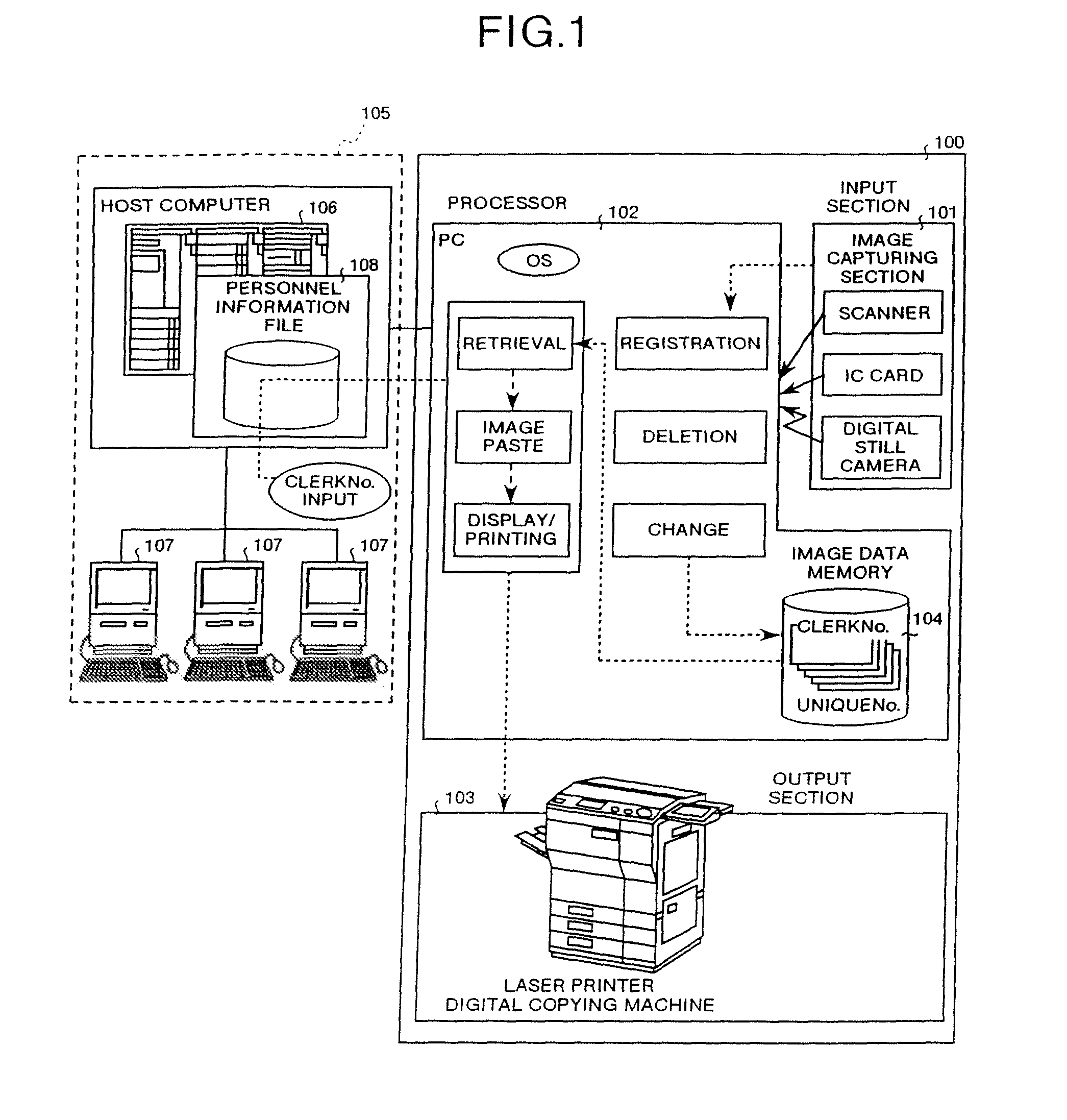
[0195]The hardware configuration of an image and document preparing system as a whole including an image processing apparatus according to Embodiment 3 of the present invention and the image processing apparatus 100 are the same as those in Embodiment 1, so that description thereof is omitted herein. The configuration of the other sections of the image processing apparatus 100 excluding the display controller 307 is also the same as those in Embodiment 1, so that description thereof is also omitted herein.

[0196]Next, description is made for the display controller 307. FIG. 14 is a block diagram functionally showing configuration of the display control and...


PUM


Abstract

An image processing apparatus according to the present invention comprises a reference image extracting section for extracting a reference image as an object for display; a parameter managing section for managing a plurality of parameters and their values for the extracted reference image; a parameter setting section for selecting any two arbitrary parameters and setting the selected parameters as scales for the vertical axis and horizontal axis; a peripheral image preparing section for preparing peripheral images each obtained by changing the values of the two parameters selected for the reference image by a specified amount; and an image display controller for providing display controls by correlating parameter values of peripheral images to those for the vertical axis and horizontal axis of the reference image so that the reference image is displayed at a specified position of a screen and also peripheral images thereof are displayed surrounding the reference image in n layers.

Description

CROSS-REFERENCE TO RELATED APPLICATIONS[0001]This application is a Continuation of and claims the benefit or priority under 35 U.S.C. §120 from U.S. Ser. No. 09 / 962,274, filed Sep. 26, 2001, which is a Divisional of U.S. Pat. No. 6,333,752, issued Dec. 25, 2001, and claims the benefit of priority under 35 U.S.C. §119 from Japanese Patent Application Nos. 10-080530, filed Mar. 13, 1998; 10-080531, filed Mar. 13, 1998; 10-080532, filed Mar. 13, 1998 and 11-045346, filed Feb. 23, 1999, respectively, the entire contents of which are hereby incorporated by reference.BACKGROUND OF THE INVENTION[0002]1. Field of the Invention[0003]2. Description of the Related Art[0004]stored in a state where the original image has been rotated by a specified angle, or a portion of the original image is separated and stored.[0005]As specific examples in which an original image is rotated by a specified angle, there is a case where, when a picture as an original image, especially a photograph showing a huma...

Claims


Application Information

Patent Timeline
Patent Type & Authority Patents(United States)
IPC IPC(8): G06F3/00H04N1/387G06F3/048G06F3/0484G06T11/60G09G5/00G09G5/14G09G5/39
CPCG06F3/04845G06T11/60G09G5/14G09G5/39
Inventor HASEGAWA, MINORUTAKAKI, TOSHINORISAKATA, NORIHIKO
Owner RICOH KK
Learn More