Elevating device for window glass

a technology of a rising device and a window glass, which is applied in the direction of door/window fittings, wing operation mechanisms, constructions, etc., can solve the problems of the unit of the window actuator misapprehending the lowermost position, the sound of knocking, etc., and achieve the effect of preventing interference with the career plate and improving the durability of the abutting portion

Inactive Publication Date: 2010-08-03
HONDA MOTOR CO LTD
View PDF10 Cites 14 Cited by
  • Summary
  • Abstract
  • Description
  • Claims
  • Application Information

AI Technical Summary

Benefits of technology

[0008]According to the elevating device for a window glass, by forming the abutting portion so as to be narrower toward a distal end side thereof, the abutting portion can actively perform an elastic deformation thereof while abutting on the guiding device. Therefore, it is possible to prevent knocking sound arised when the stopper abuts. In addition, by actively performing the elastic deformation of the abutting portion, it is also possible to prevent a setting error in the elevation-limiting position of the career plate.
[0010]In this case, by restricting the movements in the elevating direction of the step portion, it is possible to obtain a stable deformation of the abutting portion.
[0014]In this case, it is possible to prevent a shifted-abutting of the abutting portion in relation to the guiding device, and thereby enabling improvement in the durability of the abutting portion. In addition, an interference with the career plate can be prevented.

Problems solved by technology

However, in the conventional elevating device, there is a case in which knocking sound arises when the stopper abuts on the fixed member.
Also, there is a case in which a control unit of a window actuator misapprehends the lowermost position of the window glass due to insufficient elastic deformation of the stopper.

Method used


Image

  • Elevating device for window glass
  • Elevating device for window glass
  • Elevating device for window glass

Examples


Embodiment Construction

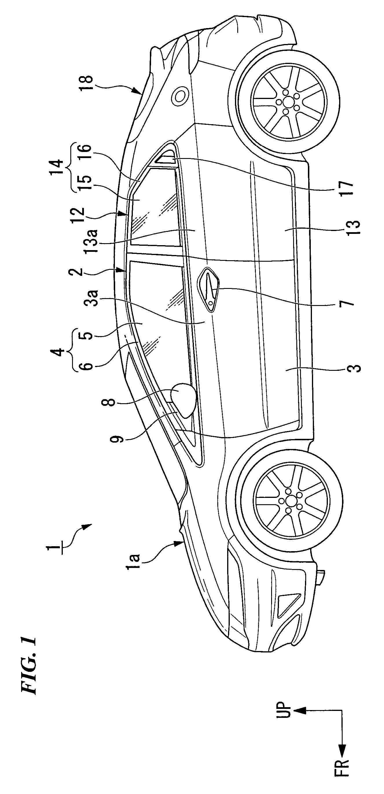
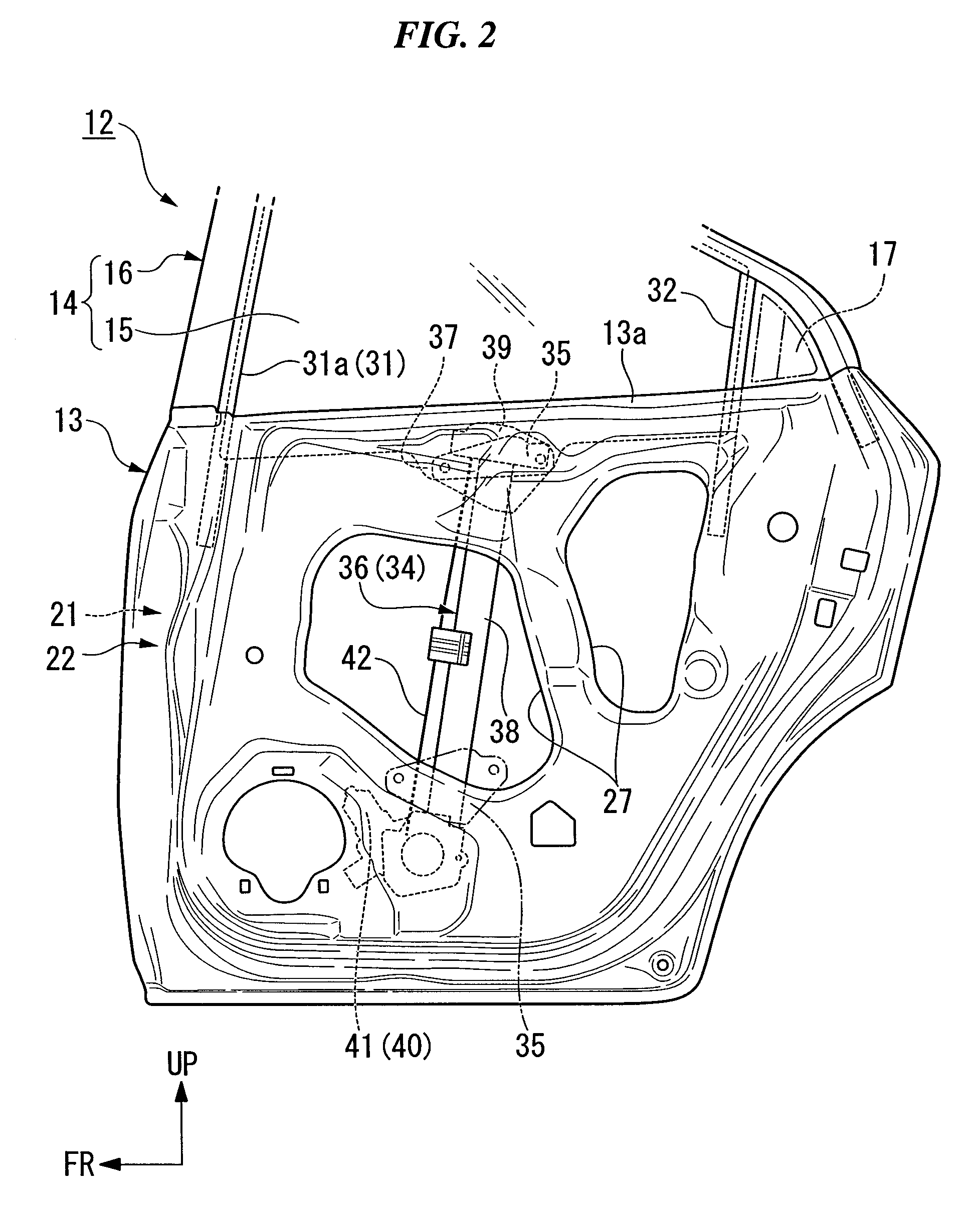
[0024]An embodiment of the present invention will be explained below with reference to the drawings. Moreover, in the following explanation, directions such as forward, backward, left, and right correspond to directions of a vehicle, if no explanation is made. In addition, in the drawings, an arrow FR denotes the forward in the vehicle direction, and an arrow UP denotes an upper direction of the vehicle.

[0025]A two-box type vehicle 1 shown in FIG. 1 is provided with a vehicle body 1a of a monocoque construction which is formed by joining panel members and a vehicle frame member so as to form one body. Openings formed in the sides of the vehicle body 1a are openable and closable by front doors 2 and rear doors 12. Each of the front doors 2 is provided with a door main body 3 forming a lower section thereof, and a window section 4 forming an upper section thereof. In addition, each of the rear doors 12 is provided with a door main body 13 forming a lower section thereof, and a window ...


PUM


Abstract

The present invention employed an elevating device for a window glass provided in a door of a vehicle, including: a guiding device which is provided in the door; a career plate which engages with the guiding device and slidably moves in an elevating direction of the window glass in relation to the guiding device; and a driving device which raises and lowers the career plate. The career plate is provided with a stopper which abuts on the guiding device when the career plate reaches an elevation-limiting position. The stopper is provided with an attaching portion which is attached to the career plate, and an abutting portion which abuts on the guiding device and elastically deforms when the stopper reaches the elevation-limiting position. The abutting portion is formed such that a width thereof becomes wider than the attaching portion and such that the width becomes smaller toward a distal end side.

Description

BACKGROUND OF THE INVENTION[0001]Priority is claimed on Japanese Patent Application No. 2005-374508, filed Dec. 27, 2005, the contents of which are incorporated herein by reference.FIELD OF THE INVENTION[0002]The present invention relates to an elevating device for a window glass, which is provided in a door of a vehicle.DESCRIPTION OF THE RELATED ART[0003]A conventional elevating device is proposed in which a stopper attached to a career plate which supports a window glass elastically abuts on a fixed member when the career plate reaches the lowermost position thereof (for example, refer to a pamphlet of PCT International Publication No. WO2002 / 075090).[0004]However, in the conventional elevating device, there is a case in which knocking sound arises when the stopper abuts on the fixed member. Also, there is a case in which a control unit of a window actuator misapprehends the lowermost position of the window glass due to insufficient elastic deformation of the stopper.[0005]The pr...

Claims


Application Information

Patent Timeline
Patent Type & Authority Patents(United States)
IPC IPC(8): E05F15/08
CPCE05F11/483E05F11/486E05F11/385E05Y2201/224E05Y2600/46E05Y2900/55
Inventor MUNEZANE, KOZOSHINKAI, TAKAHIRO
Owner HONDA MOTOR CO LTD
Why Eureka
Try Eureka