Climate chamber for microscopes

a microscope and climate chamber technology, applied in the field of climate chambers, can solve the problems of condensation risk at cold components, such as the sample carrier and in particular portions of the analysis device, and achieve the effect of high air moisture and rapid variation of the opening cross section

Active Publication Date: 2010-08-03
EVOTEC TECH GMBH
View PDF35 Cites 10 Cited by
  • Summary
  • Abstract
  • Description
  • Claims
  • Application Information

AI Technical Summary

Benefits of technology

[0006]Further, the climate chamber according to the invention comprises an inlet opening through which a conditioning medium flow can be introduced into the climate chamber. In particular air with, for example, a defined air moisture and / or temperature is introduced. If necessary, gases contained in the air, such as CO2, can be defined. Since the medium flow can in particular have a relatively high air moisture for increasing the air moisture in the climate compartment, there is the risk of condensation at cold components, such as the sample carrier and in particular portions of the analysis device. Since condensation at such components may lead to a considerable falsification of the analysis results, the invention provides for the medium flow to be introduced into the climate compartment such that at least a portion of the medium flow flows against the analysis device and / or the sample carrier. Preferably, the flow flows against both the sample carrier and the critical components of the analysis device. Thus, condensation in this region is prevented.
[0025]Further, the climate control device according to the invention may comprise a conditioning means for heating and / or cooling the conditioned medium. The conditioning means is preferably arranged downstream of the steam chamber such that medium freshly charged with steam subsequently flows through the conditioning means. Provision of a conditioning means which can also be used for cooling purposes, if necessary, offers the advantage that the medium temperature, which has been increased by the introduction of steam, can be decreased again if such a temperature increase is undesired. It is thus possible to control the moisture content of the medium within large ranges independent of the medium temperature. The range is substantially limited by physical limitations, i.e. in particular the ability of the medium to absorb moisture as a function of the temperature (dew point). Tests have shown that the fluid, which is present in the steam chamber for evaporation purposes, is preferably adjusted to a temperature of 40-65° since otherwise too large an influence is exerted on the temperature of the medium to be conditioned, and extensive cooling would be necessary. The cooling process further allows the temperature to be kept below 30° at a high moisture of preferably 90%.

Problems solved by technology

Since the medium flow can in particular have a relatively high air moisture for increasing the air moisture in the climate compartment, there is the risk of condensation at cold components, such as the sample carrier and in particular portions of the analysis device.

Method used


Image

  • Climate chamber for microscopes
  • Climate chamber for microscopes
  • Climate chamber for microscopes

Examples


Embodiment Construction

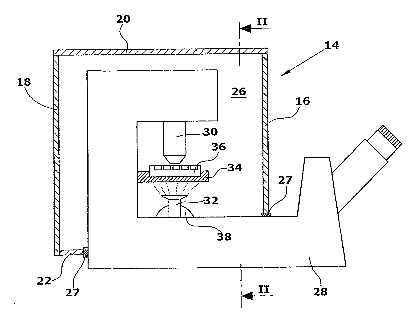
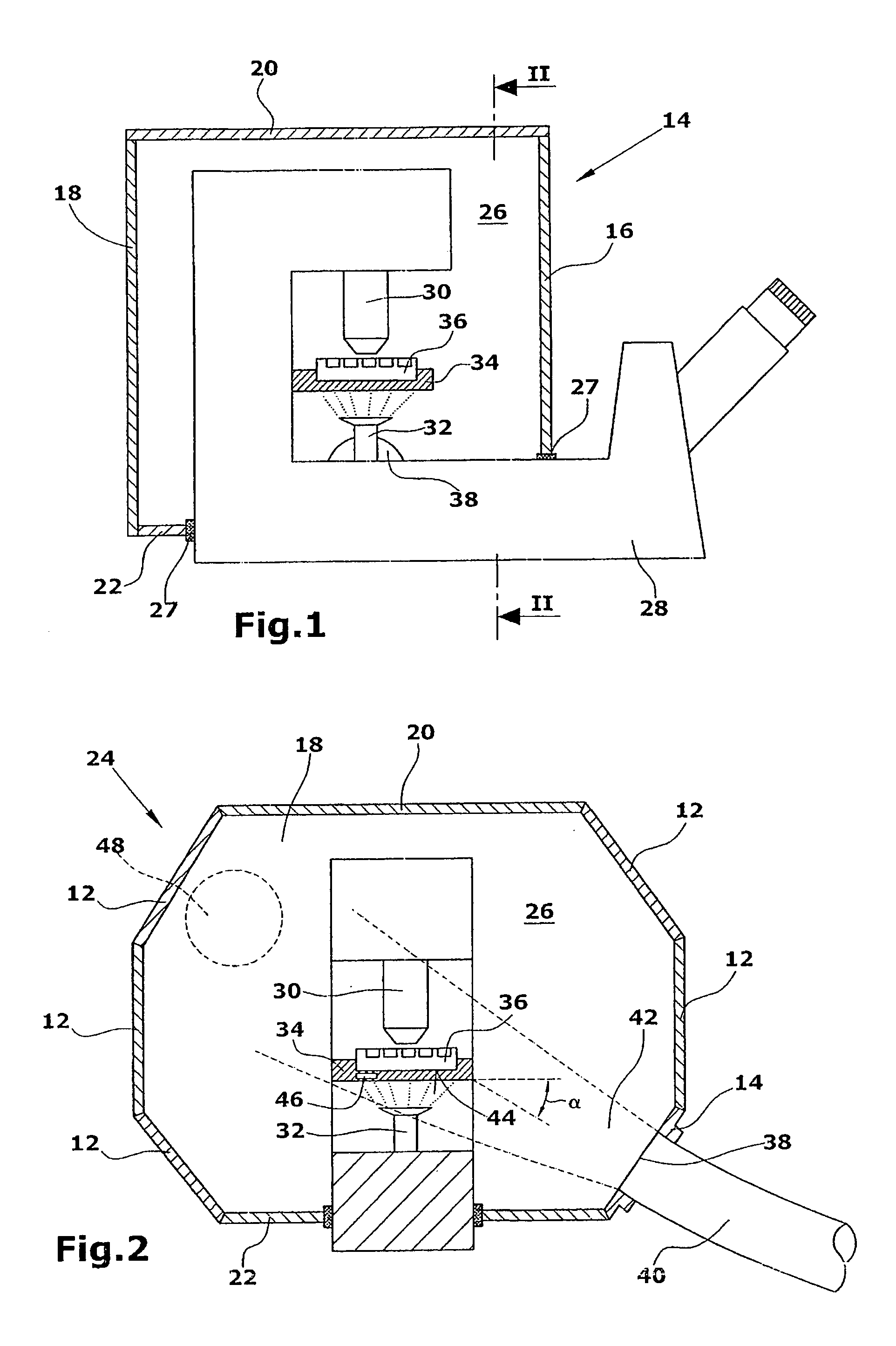
[0033]A climate chamber comprises a plurality of side walls 12,14 (FIG. 2), a front wall 16 (FIG. 1), a rear wall 18, a top wall 20 and a bottom wall 22. The walls 12-22 form a housing 24 which defines a climate compartment 26. The housing 24 comprises a bottom wall 22 and a recess in the front wall 16 such that the housing 24 can be placed upon a microscope 28. The front wall 16 and the bottom wall 22 comprise sealing elements 27 which bear against the analysis device or the microscope 28 and substantially tightly seal the climate compartment 26 towards the outside. Essential components of the analysis device, which in the illustrated embodiment is a microscope 28, are thus arranged inside the climate compartment 26. These components are in particular an optical means 30 normally comprising a plurality of lenses, and an illumination means 32. Further, a sample table 34, which is normally of displaceable configuration, and a sample carrier 36, which is in particular a microtiter pla...


PUM

PropertyMeasurementUnit
angleaaaaaaaaaa
flow approach angleaaaaaaaaaa

Abstract

A climate chamber, which is in particular suitable for chemical and / or biological samples, comprises a climate compartment defined by a housing. Inside the climate compartment an analysis device, such as a microscope, is at least partially arranged. Further, the housing comprises an inlet opening for supplying a conditioning medium flow. For preventing condensation at condensate-sensitive components the medium flow is directed such that it at least partially flows against the analysis device and / or the sample carrier.

Description

FIELD OF THE INVENTION[0001]The invention relates to a climate chamber which is in particular suitable for chemical and / or biological samples.DISCUSSION OF THE BACKGROUND ART[0002]In the case of chemical and / or biological samples, such as cells, it is necessary, for example for analyzing the cell growth or other reactions, to expose the sample to a defined climate over a longer period. With regard to the climate, in particular the temperature and the moisture content in a climate compartment, where the sample is arranged, are of great importance. Further, gas constituents, such as the quantity of CO2 etc., may be relevant.[0003]From JP 2003107364 a climate chamber is known in which a sample carrier is arranged. The defined climate compartment exclusively encloses the sample carrier and comprises a transparent cover which allows the sample to be analyzed or observed with the aid of an analysis device, such as a microscope. Provision of such a climate chamber has the drawback that the...

Claims


Application Information

Patent Timeline
Patent Type & Authority Patents(United States)
IPC IPC(8): G01N21/01G01D11/24B01L1/00G02B21/24
CPCB01L1/00C12M41/36C12M23/48C12M23/54C12M41/14G02B21/24B01L2300/10B01L2300/1838
Inventor PIRSCH, MATTHIASHUMMEL, STEFAN
Owner EVOTEC TECH GMBH
Why Eureka
Try Eureka