Liquid dispensing method and device

Inactive Publication Date: 2008-10-21
HITACHI LTD +1
View PDF44 Cites 6 Cited by
  • Summary
  • Abstract
  • Description
  • Claims
  • Application Information

AI Technical Summary

Benefits of technology

[0009]An object of the present invention is to provide a liquid handling method and apparatus suitable to keep the

Problems solved by technology

As already explained, the method comprising the steps of drawing a preset amount of water into a tip by suction and drawing a sample liquid into the tip by ejecting the w

Method used


Image

  • Liquid dispensing method and device
  • Liquid dispensing method and device
  • Liquid dispensing method and device

Examples


Embodiment Construction

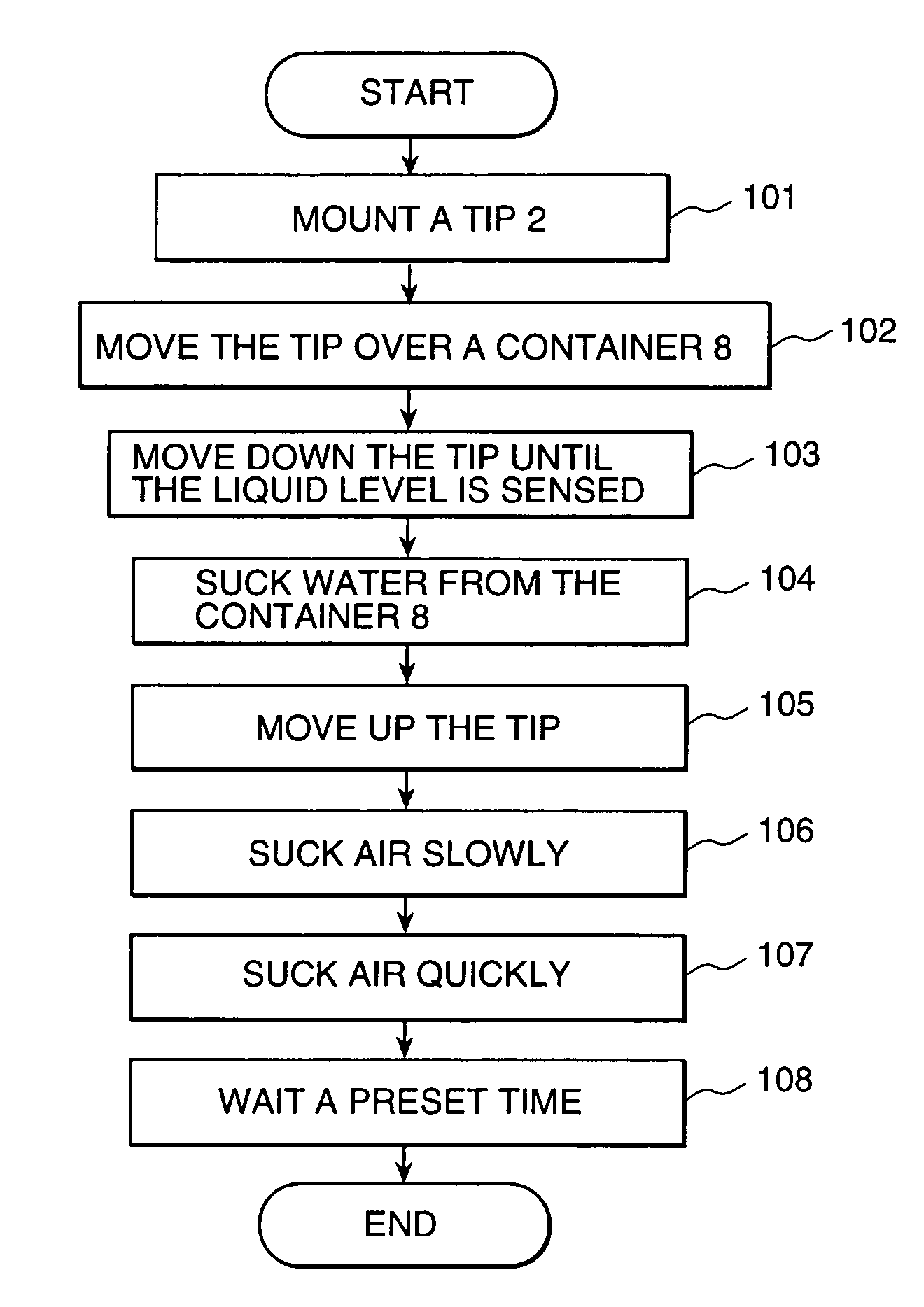
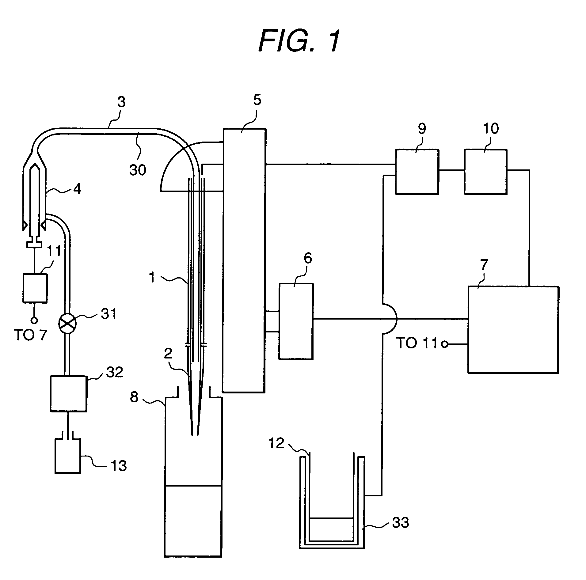
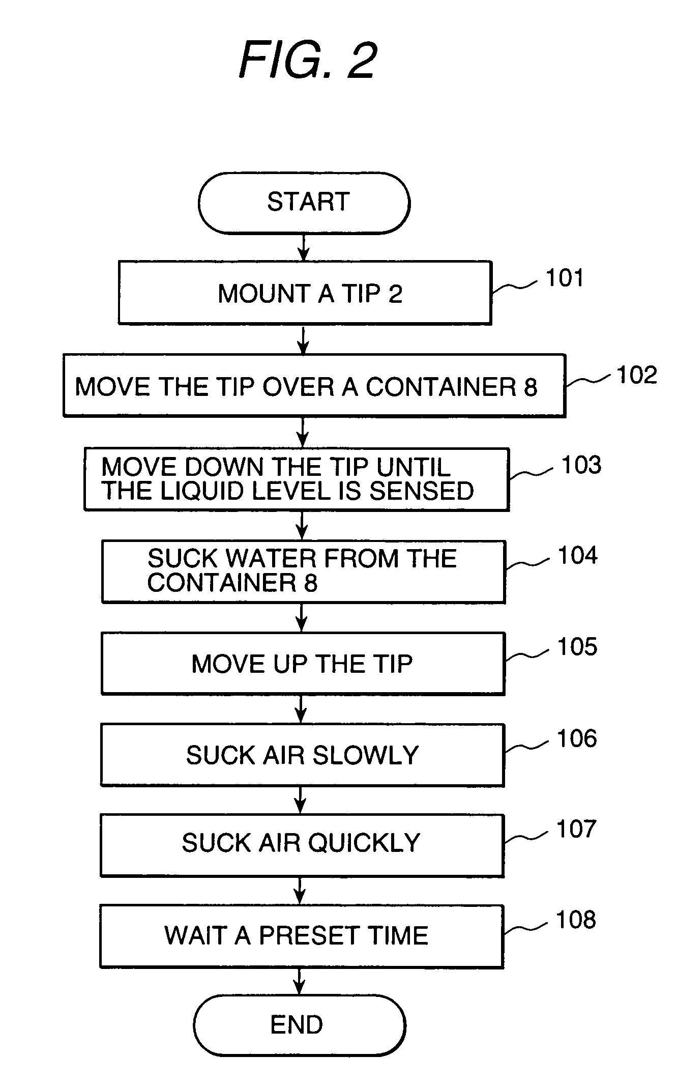
[0019]FIG. 1 is a schematic diagram of a liquid handling apparatus according to one embodiment of the present invention. A conductive pipetting probe 1 has a conductive tip 2 on the lower end of the probe 1. The probe 1 is connected to a syringe 4 with a tube 3. The syringe 4 is driven by a syringe driving mechanism 11 which is controlled by a control section 7. A pump 32 pumps up water from a water tank 13 to fill the syringe 4, the tube 3, and the probe 1 with water prior to pipetting of a sample liquid. A valve 31 is opened to fill them with water. Water is used as medium to transmit operation of the syringe 4 to a sample liquid when drawing a sample liquid into a tip 2 by suction and ejecting the sample liquid from the tip 2. The transmitting medium is assigned a symbol 30 in the accompanying drawings.

[0020]A probe lifting and transferring mechanism 5 driven by a motor 6 can move the probe up and down and the motor 6 is controlled by a control section 7. The probe 1 horizontally...


PUM


Abstract

A method of pipetting an accurate quantity of liquid comprising the steps of drawing water into a pipetting chip (2) from a liquid container (8), drawing air into said tip first slowly at a first rate and then quickly at a second rate to turn said drawn water into a mist of drops in said tip (2) and increase the relative humidity of the air in said tip (2), waiting a preset time period, and drawing a tested liquid into said tip (2).
This makes the quantity of vapor of the tested liquid in said tip (2) very small and constant and thus the accurate quantity of tested liquid can be pipetted.

Description

TECHNICAL FIELD[0001]The present invention relates to a liquid handling method and a liquid handling apparatus, particularly to a liquid handling method and a liquid handling apparatus suitable for an automatic analyzing apparatus.BACKGROUND ART[0002]An automatic analyzing apparatus which pipettes a reagent and a sample into a reaction container and measures the reactant liquid is equipped with a liquid handler which pipettes reagents and samples into reaction containers.[0003]This liquid handler employs a method of using a pipetting probe made of stainless steel to directly pipette a sample or a reagent, washing the probe which touched a sample or a reagent after pipetting, and using the probe again for next pipetting or a method of applying a disposable tip to a pipetting probe before pipetting and replacing the tip by a new one after pipetting. The method of using a disposable tip can avoid liquid carry-overs between samples, between reagents, and between sample and reagent. As c...

Claims


Application Information

Patent Timeline
IPC IPC(8): G01N1/10B01L3/02G01N35/10
CPCB01L3/021G01N35/1016B01L3/0241B01L2200/14Y10T436/25G01N2035/1025Y10T436/2575B01L2300/10
Inventor TOKIWA, YUKIEIMAI, KYOKOSIEGFRIED, LOTTERERFRIEDEMANN, KRAUSE
Owner HITACHI LTD
Why Eureka
Try Eureka