Device for damping the needle lift in fuel injectors

a technology of fuel injector and needle lift, which is applied in the direction of fuel injection apparatus, fuel injection with sensors, charge feed systems, etc., can solve the problems of increasing the structural complexity and therefore the cost of the injection system, and the inability to achieve the pressure level of the accumulator injection system in use today, and achieving the pressure level is currently limited

Inactive Publication Date: 2005-04-14
ROBERT BOSCH GMBH
View PDF2 Cites 19 Cited by
  • Summary
  • Abstract
  • Description
  • Claims
  • Application Information

AI Technical Summary

Benefits of technology

[0010] The needle opening speed can be adjusted by means of appropriately dimensioning the flow cross sections and the lengths of the throttle restrictions of the inlet and outlet throttles. The closing speed of the nozzle needle is essentially determined by the cross-sectional area of the outlet throttle. It is thus possible, in principal, to set the opening speed and closing speed of the nozzle needle independently of each other through the dimensioning of the inlet throttle and outlet throttle and thus on the one hand, to achieve a slow opening of the injection valve element, e.g. a nozzle needle, and on the other hand, to achieve a rapid closing of the injection valve element of the fuel injector. A rapid closing of the injection valve element of a fuel injector permits an improvement in the emission levels of an autoignition internal combustion engine. A rapid closing of the injection valve element assures that a precisely defined termination point of the injection can be maintained, thus preventing subsequent injection of fuel into the combustion chamber, which would no longer be transformed during the combustion and would be contained in the exhaust in the form of unspent fuel and have an extremely negative influence on the HC content of this exhaust.
[0011] The production of a rapid needle closing also offers the possibility of keeping the quantity characteristic curve flat in the ballistic operating state of the nozzle, i.e. during the movement between its stroke stops and / or the injection valve element seat, which considerably improves the fuel metering precision.
[0012] The fact that the proposed concept of a stroke damping does not require additional moving parts, but merely makes use of the flow routing, means that inertial influences of the kind that come into play with the use of an additional precision component are not an issue, thus permitting the execution of multiple injection events—even those that follow one another in rapid succession—since restoring times of mechanical components do not have to be taken into account in the time intervals between injection phases. In order to prevent the occurrence of high diversion quantities, which would escape through the inlet and outlet valves and have a negative influence on the hydraulic efficiency, the injection valve element, upon reaching its maximal stroke, can advantageously close the inlet throttle completely. As a result, a leakage via this throttle restriction flows only during the short opening phase of the injection valve element.
[0013] One advantageous possible embodiment is characterized in that a high-pressure chamber of a pressure booster without an additional check valve can be filled via the throttle restrictions. This makes it possible to embody both the needle stroke damper and the valve for filling the high-pressure chamber with a low degree of structural complexity.
[0014] In one variant of the design proposed according to the invention, the fuel injection apparatus can be triggered by means of a 2 / 2-way valve. This permits the achievement of an inexpensive overall construction, in this case allowing a pressure compensation to occur either by means of a filling throttle or by means of a pressure-reduction valve.
[0015] The design proposed according to the invention permits the achievement of a pressure-controlled opening of the injection valve element, which occurs at a speed that permits a favorable vaporization of the fuel during the injection into the combustion chamber. A favorable vaporization of the injected fuel facilitates the production of a homogeneous mixture of fuel and combustion air. A stroke-controlled closing of the injection valve element, which can be hydraulically influenced, improves the minimum quantity capacity during preinjections and secondary injections of the fuel injector and prevents a blowback of combustion gases to the seat region of the injection valve element, e.g. a nozzle needle.

Problems solved by technology

The achievable pressure level in accumulator injection systems in use today is currently limited to approximately 1600 bar for strength reasons.
In pressure-controlled common rail injection systems with pressure boosters, the problem arises that it is not possible to assure the stability of the injection quantities to be injected into the combustion chamber, particularly when producing very small injection quantities, for example during preinjection.
Although this design does in fact permit a reduction in the needle opening speed, it increases the structural complexity and therefore the cost of the injection system quite considerably.

Method used


Image

  • Device for damping the needle lift in fuel injectors
  • Device for damping the needle lift in fuel injectors
  • Device for damping the needle lift in fuel injectors

Examples


Embodiment Construction

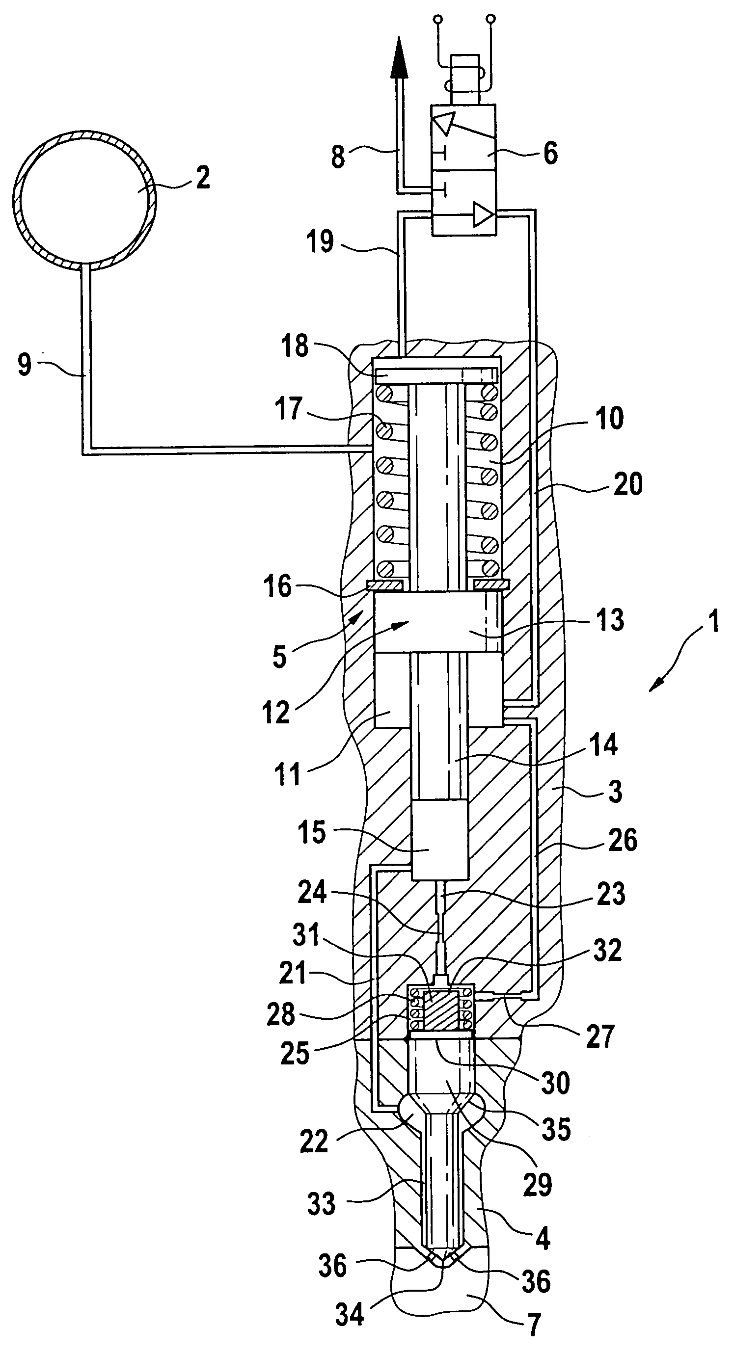
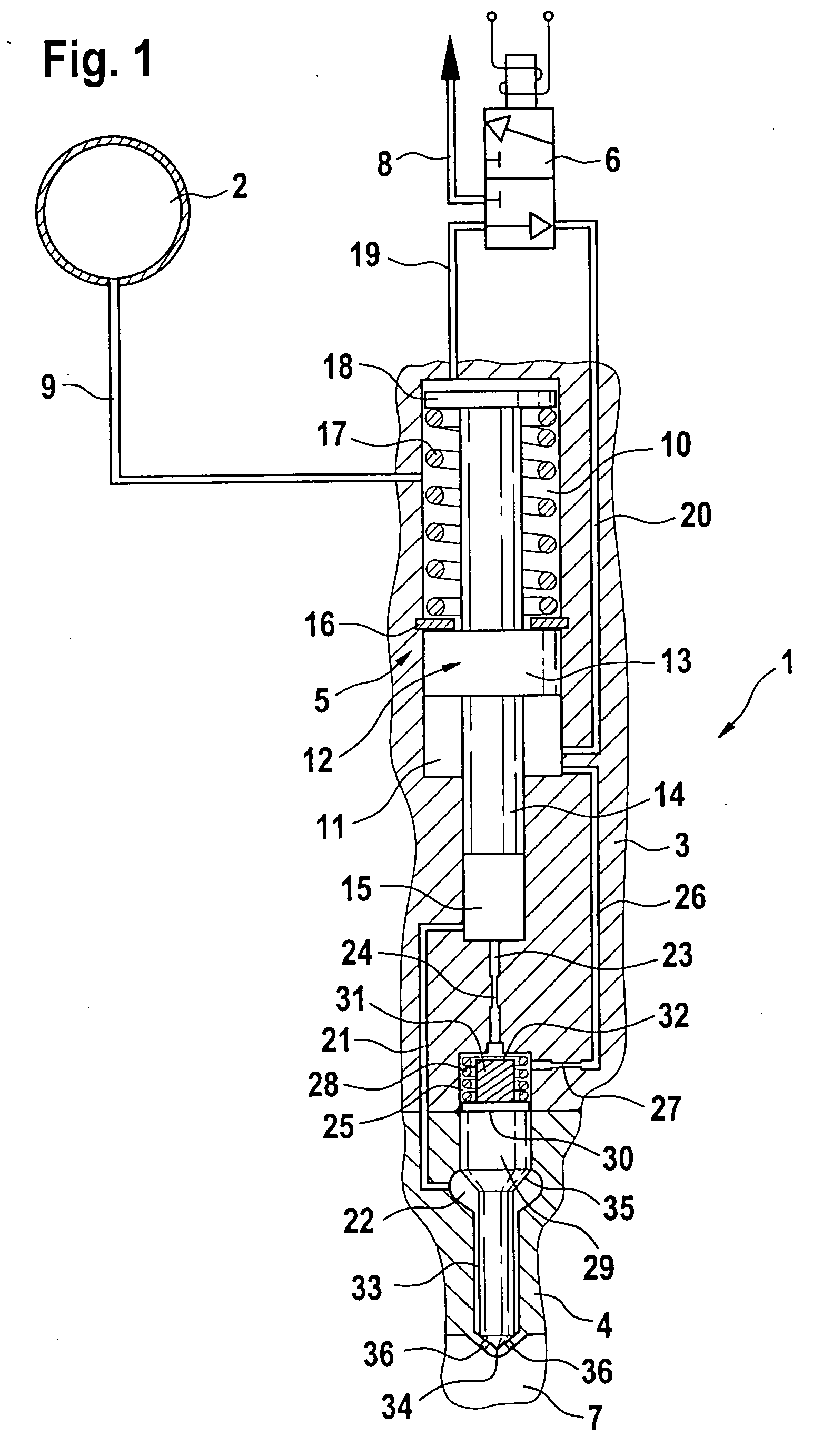
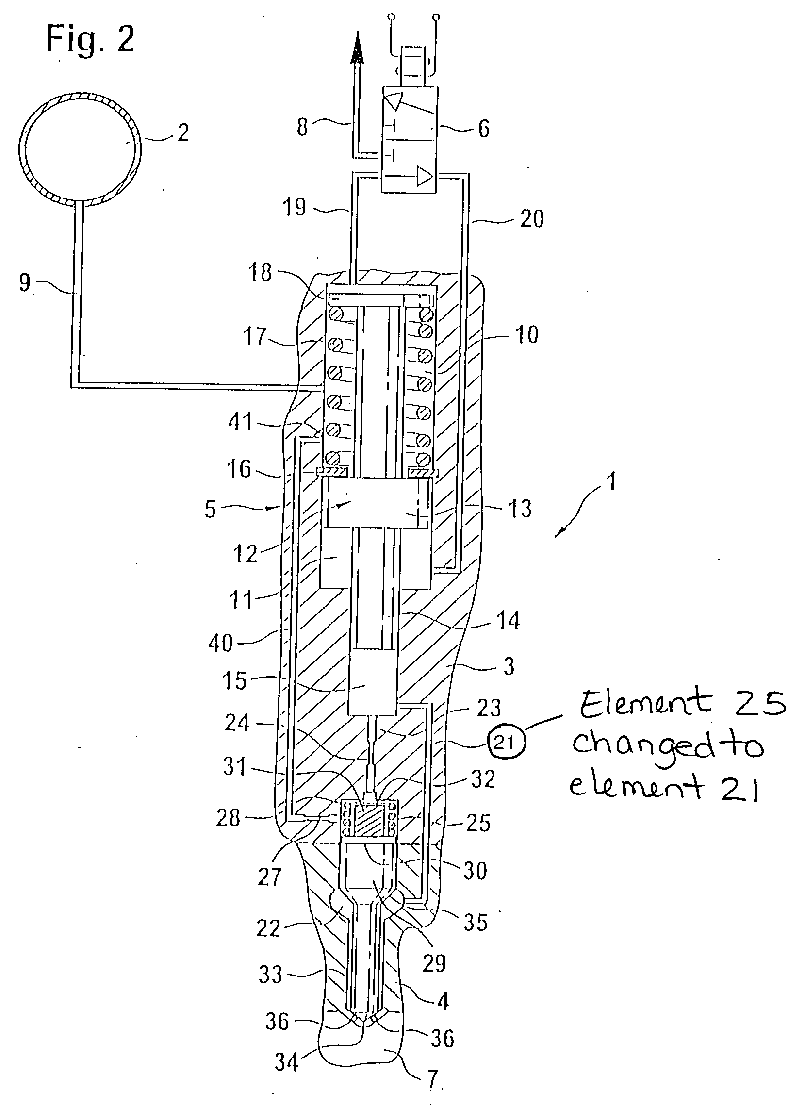
[0009] With the design proposed according to the invention, it is possible to eliminate the use of a precision component as mentioned above, for example a needle stroke damper piston, by executing the function of the needle stroke damping by means of a flow through the nozzle needle spring chamber. On the one hand, the proposed design permits a significant reduction in the technical manufacturing complexity and on the other hand, it significantly improves the minimum quantity capacity of the fuel injector by reducing the needle opening speed. A separate precision component in the form of a needle stroke damper piston is not required. Instead, the nozzle spring chamber of the nozzle needle is filled from the high-pressure side via an inlet throttle or is pressure-relieved to the low-pressure side or to the working chamber via an outlet throttle.

[0010] The needle opening speed can be adjusted by means of appropriately dimensioning the flow cross sections and the lengths of the thrott...


PUM


Abstract

A fuel injection apparatus for injecting fuel into the combustion chambers of an internal combustion engine includes a high pressure accumulator, a pressure booster, and a metering valve. The pressure booster includes a working chamber and a control chamber that are separated from each other by an axially movable piston. A pressure change in the control chamber produces a pressure change in a compression chamber that acts on a nozzle chamber via a fuel inlet. The nozzle chamber encampasses a nozzle needle. A nozzle spring chamber that acts on the injection valve element can be filled on the high-pressure side via a line that leads from the compression chamber and contains an inlet throttle restriction. On the outlet side, the nozzle spring chamber is connected to a chamber of the pressure booster via a line that contains an outlet throttle restriction.

Description

TECHNICAL FIELD [0001] It is possible to use both pressure-controlled and stroke-controlled injection systems to supply fuel to combustion chambers of autoignition internal combustion engines. In addition to unit fuel injectors, these fuel injection systems are also embodied in the form of unit pumps and accumulator injection systems. Accumulator injection systems (common rails) advantageously permit the injection pressure to be adapted to the load and engine speed. It is generally necessary to achieve the highest injection pressure possible in order to achieve high specific loads and reduce engine emissions. PRIOR ART [0002] The achievable pressure level in accumulator injection systems in use today is currently limited to approximately 1600 bar for strength reasons. In order to further increase pressure in accumulator injection systems, these common rail systems make use of pressure boosters. [0003] EP 0 562 046 B1 has disclosed an actuation / valve apparatus with damping for an ele...

Claims


Application Information

Patent Timeline
Patent Type & Authority Applications(United States)
IPC IPC(8): F02M45/00F02M61/10F02M47/00F02M47/02F02M55/02F02M57/02F02M59/10F02M61/16F02M61/20F02M63/00
CPCF02M57/025F02M59/105F02M2200/304F02M2200/24F02M61/205
Inventor KROPP, MARTINMAGEL, HANS-CHRISTOPHMACK, MANFREDGRIMMINGER, CHRISTIAN
Owner ROBERT BOSCH GMBH
Why Eureka
Try Eureka