Temperature and humidity air treatment system

a technology of air treatment system and temperature and humidity, which is applied in the direction of defrosting, heating type, heating apparatus, etc., can solve the problems of inconvenient control, inconvenient use, and inconvenient use of equipmen

Inactive Publication Date: 2014-11-04
ISAACSON ROLAND H
View PDF22 Cites 7 Cited by
  • Summary
  • Abstract
  • Description
  • Claims
  • Application Information

AI Technical Summary

Problems solved by technology

High humidity levels can cause condensation inside homes and human environmental discomfort.
Many of these depended on reheating the cooled air either by use of additional heat from the oil or gas furnace or electric heat, both of which are cost prohibitive.
Other approaches have included multiple evaporators and condensers but these were often difficult to control and required complex controls both for the temperature and the storage of refrigerant.
The reduction in fan air volume reduces the heating effect of the air passing over the evaporator which in turn lowers the temperature of the evaporator.
The increased size of the evaporator has reduced the ability of the air conditioning system to remove moisture from the air resulting in higher humidity levels.

Method used


Image

  • Temperature and humidity air treatment system
  • Temperature and humidity air treatment system
  • Temperature and humidity air treatment system

Examples


first embodiment

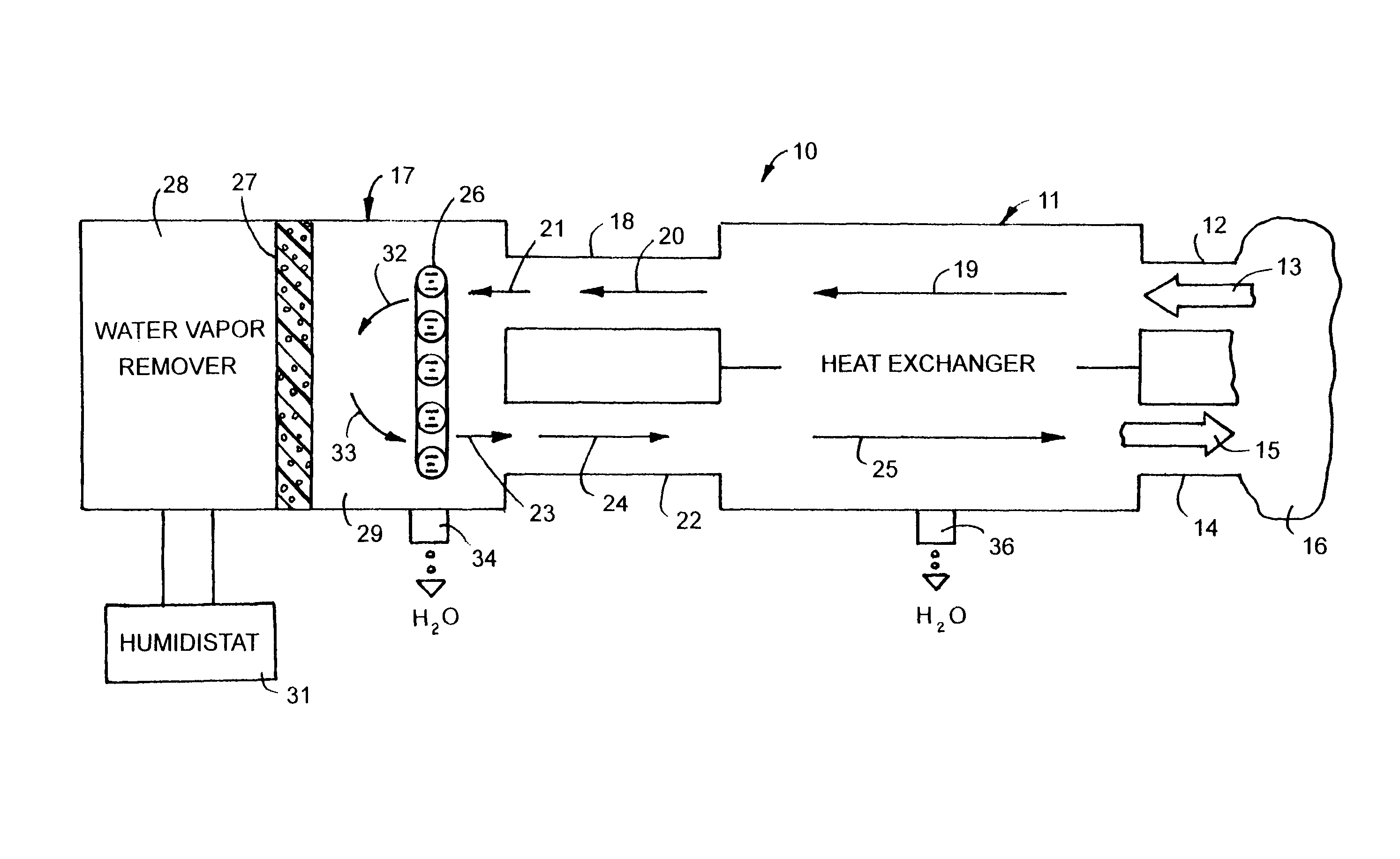
[0013]the temperature and humidity air treatment system 10, shown in FIG. 1, has a heat exchanger 11 combined with a water vapor remover 17 operable to control the temperature and humidity of air in an interior environment or enclosure 16, such as a residential, an office room or other enclosed environments. Dampers can be used to control the flow of air into a plurality of interior environments. Heat exchanger 11 is a device designed for the efficient transfer of heat from one fluid to another fluid over a solid surface. The transfer of heat is in the form of absorption from warm air to cooled air to reduce atmospheric air temperature and humidity in interior enclosure 16. The atmosphere is a mixture of air and water vapor. When the atmosphere is cooled under constant total pressure, the air pressure remains constant until a dew point temperature is reached at which condensation of water vapor begins and the air temperature decreases. Relative humidity RH is the ratio of the actual...

second embodiment

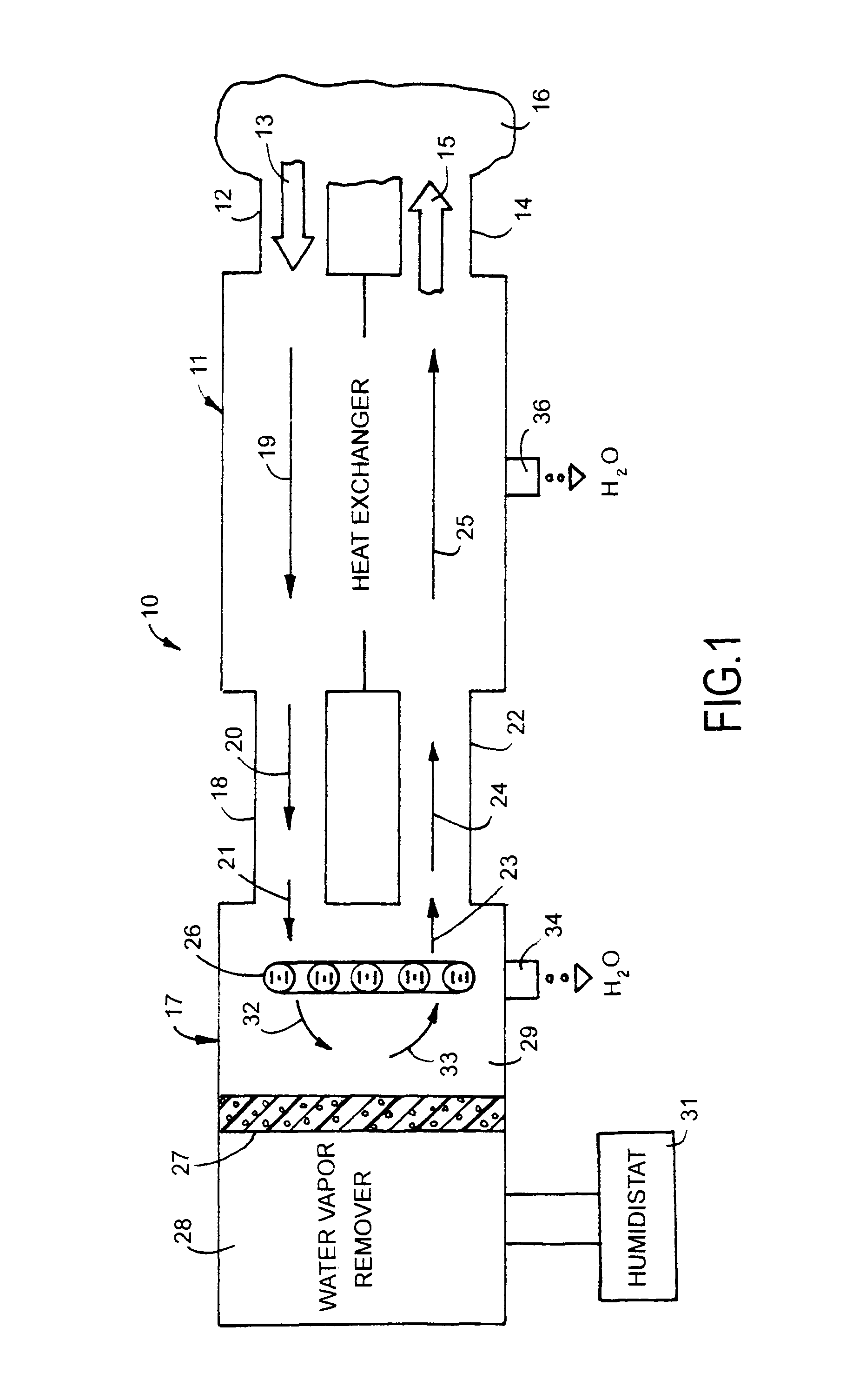
[0018]the humidity air treatment system 100, shown in FIG. 2, has a heat exchanger 111 combined with a water vapor remover 117 to regulate the air temperature and humidity of the air within an interior environment or enclosure 116, such as one or more rooms of a building. Dampers can be used to control the flow of air into more than one interior environment. The parts and functions of heat exchanger 11 and water vapor remover 17 shown in FIG. 1 are applicable to system 100 and are incorporated herein. The parts of system 100 that correspond to system 10 have the same reference number with the prefix 1.

[0019]Heat exchanger 111 has an air inlet duct 112 that allows air to flow, shown by arrow 113, into heat exchanger 111. A motor driven blower 137 pumps atmospheric air shown by arrow 138 into heat exchanger 111. The motor can be wired to humidistat 131 whereby humidistat located in interior enclosure 116 controls the operation of the motor that drives blower 137 in response to the rel...

third embodiment

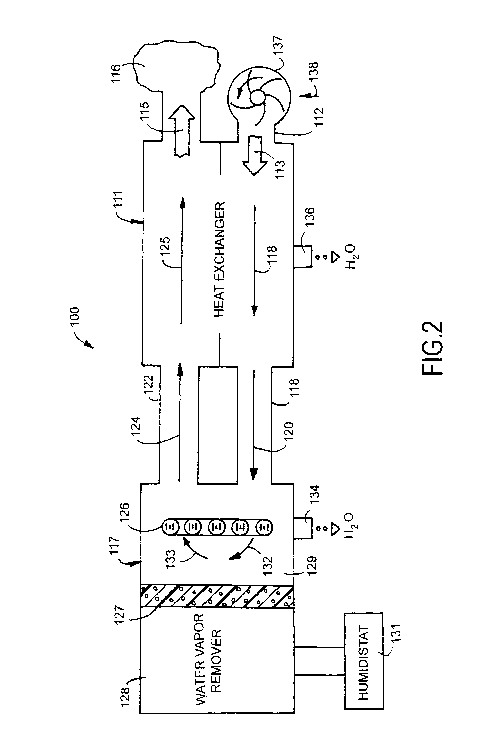
[0020]the humidity air treatment system 200, shown in FIG. 3, has a heat exchanger 211 combined with a water vapor remover 217 to regulate the air temperature and humidity of the air within an interior environment or enclosure 216, such as one or more rooms of a building. The parts and functions of heat exchanger 11 and dehumidifier 17 shown in FIG. 1 are applicable to system 200 and as incorporated herein. The parts of system 200 that correspond to system 10 have the same reference numbers with the prefix 2. A motor driven blower 237 operates to discharge warm atmospheric air 238 into heat exchanger 211, shown by arrow 213. Blower 237 can be located to move air from enclosed environment 216 to heat exchanger 211. Blower 237 can be placed in different locations and structures relative to heat exchanger 211 and water vapor remover 217 to achieve effective air flow through heat exchanger 211 and water vapor remover 217. The PCMs or refrigerant in coils 226 cools the air flowing throug...


PUM


Abstract

A temperature and humidity air treatment system for air directed to an enclosed environment has a heat exchanger joined with a water vapor remover having a phase change material to cool air and condense water vapor in the air and subsequently heat the cool air by absorbing heat from humid warm air flowing through the heat exchanger.

Description

CROSS REFERENCE TO RELATED APPLICATION[0001]This application claims the benefit of the priority of U.S. Provisional Patent Application Ser. No. 61 / 401,143 filed Aug. 9, 2010.FIELD OF THE INVENTION[0002]The invention relates to temperature and humidity treatment of air for interior enclosures. A heat exchanger associated with water vapor remover reduces the temperature and humidity from air supplied to an interior environment.BACKGROUND OF THE INVENTION[0003]Comfort is a relative term that is different for virtually every individual because of sex, age, ethnicity, and activity level. Comfort is tied not only to the temperature but also to the relative humidity of an environment. Scientists have also found that a humidity level between 30 and 50 percent discourages many types of mold, dust mites, allergens, and certain bacteria. High humidity levels can cause condensation inside homes and human environmental discomfort.[0004]Air conditioning and heating systems have been designed to r...

Claims


Application Information

Patent Timeline
Patent Type & Authority Patents(United States)
IPC IPC(8): F25D17/06
CPCF24F11/0015F24F2003/144F25D17/06F24F2003/1446F24F3/153F24F3/14F24F5/0021F24F11/30F24F2110/20Y02E60/14
Inventor ISAACSON, ROLAND, H.
Owner ISAACSON ROLAND H
Why Eureka
Try Eureka