Transmitting and receiving methods

a technology of receiving method and transmission method, which is applied in the direction of amplitude demodulation, line-faulst/interference reduction, baseband system details, etc., can solve the problem that the blast type modulation system cannot reach the channel capacity, and the controllers are complex to control both the transmission and receiving elements

Active Publication Date: 2010-08-10
NOKIA TECHNOLOGLES OY
View PDF26 Cites 184 Cited by
  • Summary
  • Abstract
  • Description
  • Claims
  • Application Information

AI Technical Summary

Benefits of technology

[0023]Within such a system embodying the present invention the performance in terms of given throughput, with bound conditions set by allowed maximum complexity, may be equal or better than the prior art. Also embodiments of the invention may be scalable so that the communications system can be applied to work for different numbers of transmit and receive antennas and different sizes of modulation alphabets. Embodiments of the invention may be also adaptable to various degrees of antenna correlation, from completely uncorrelated antennas in a rich scattering environment, to a near-completely correlated (line of sight) environment.

Problems solved by technology

These systems require complex controllers to control both the transmission and receiving elements of both the base station and the mobile station.
This is especially complex where the communications equipment differs in capacity between base station to base station and user equipment to user equipment and from time to time.
This document though does not address the problem of controlling a MIMO system, where users with different equipment and requirements can co-exist within the same system, and base stations may have different capabilities.
Where this is not true the BLAST type modulation system is unable to reach the channel capacity.

Method used


Image

  • Transmitting and receiving methods
  • Transmitting and receiving methods
  • Transmitting and receiving methods

Examples


Embodiment Construction

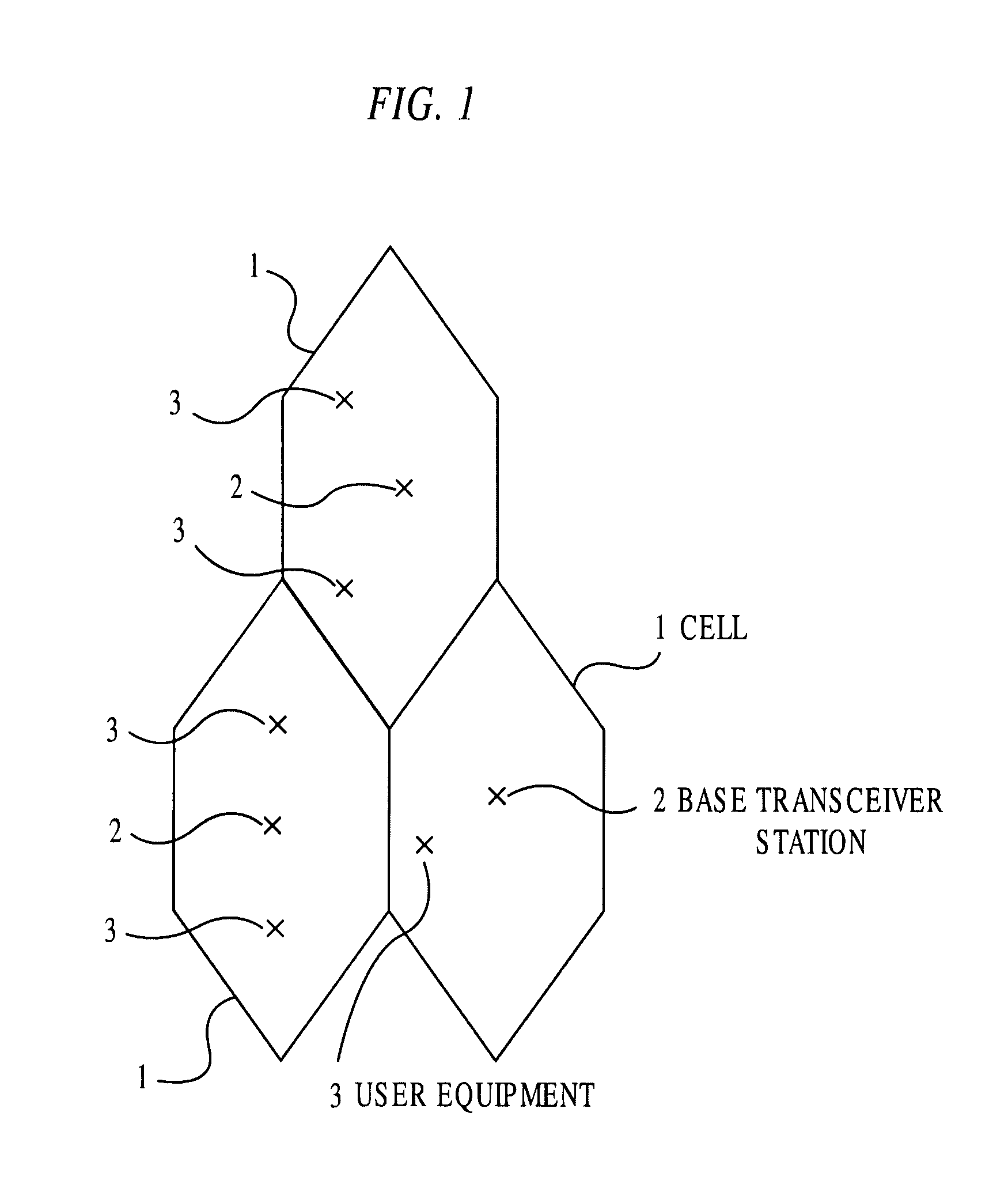
[0033]Reference is made to FIG. 1, which shows part of a cellular telecommunications network in which embodiments of the present invention can be implemented. The area covered by the network is divided into a plurality of cells 1, only three of which are shown in totality with other cells bordering these complete cells. Each cell 1 has associated therewith a base transceiver station 2. The base station transceiver 2 is arranged to communicate with mobile terminals or other user equipment 3 located in the cell associated with a base station. The cells 1 may overlap at least partially or totally. In some systems, the cells 1 may have different shapes to that illustrated. In some embodiments the base stations 2 may communicate with mobile stations 3 outside their associated cell.

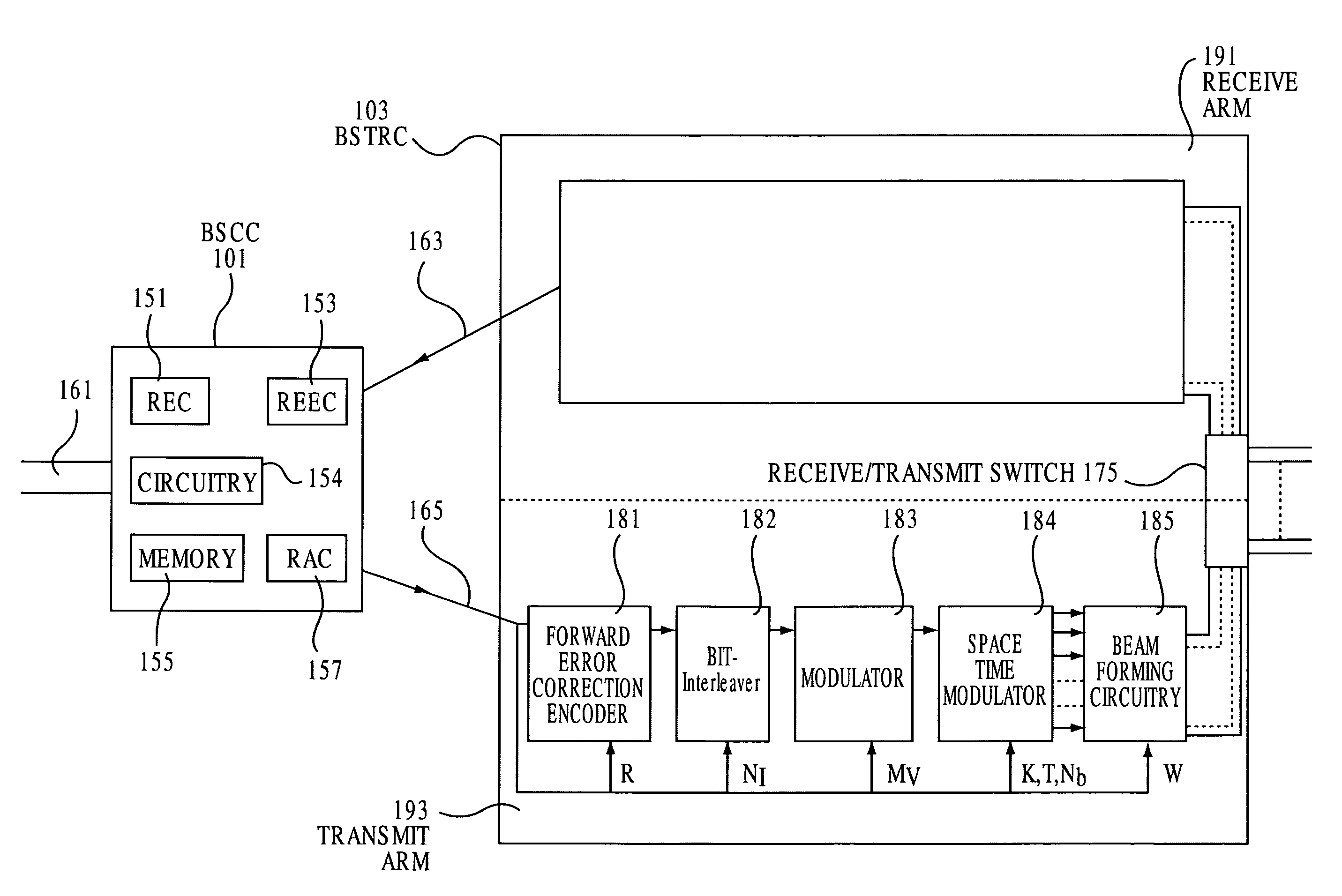
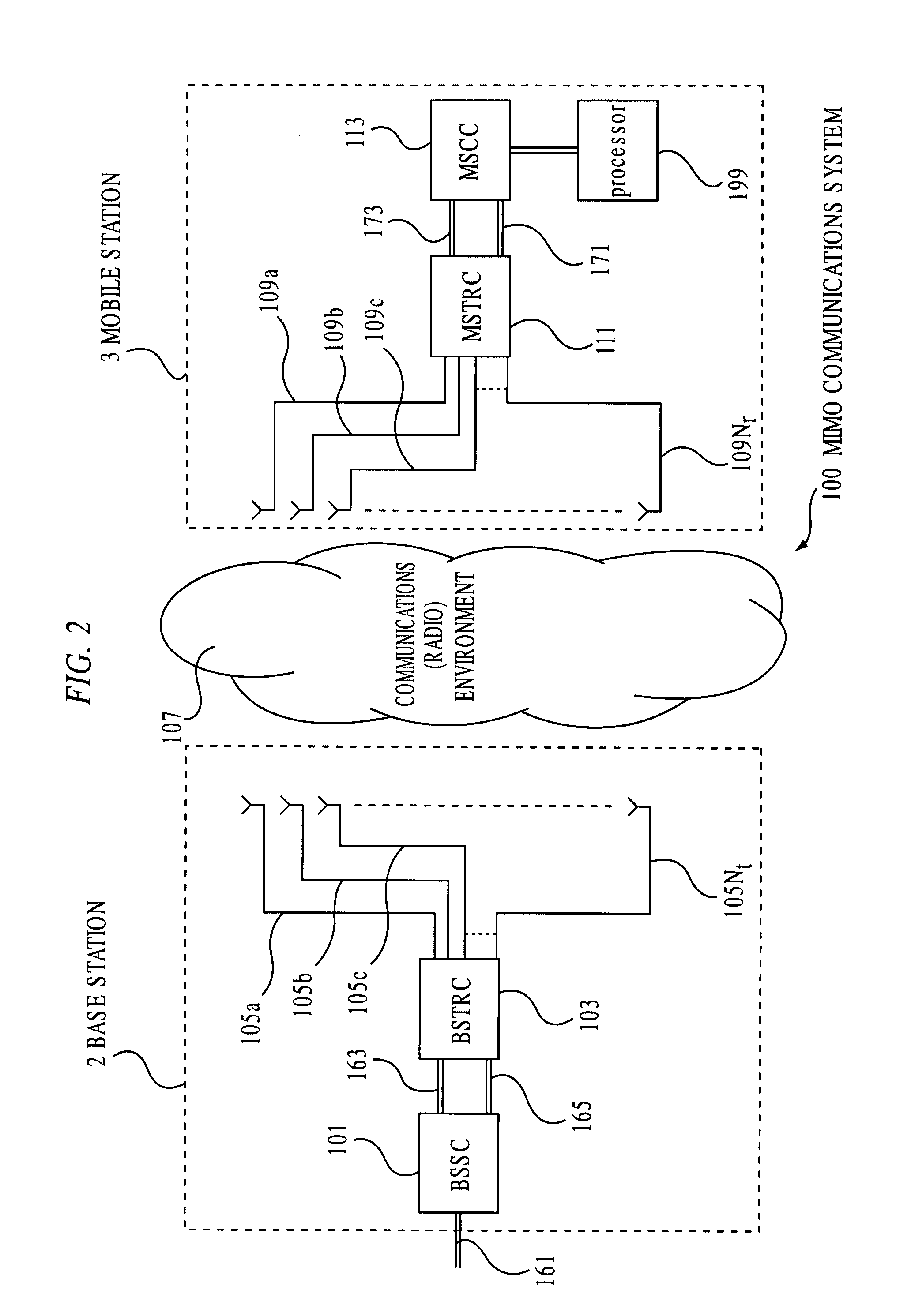
[0034]Reference is now made to FIG. 2 which shows the principles behind a typical multiple input multiple output (MIMO) communications system 100, which may be incorporated into a cellular telecommunications ne...


PUM


Abstract

This invention describes a wireless system comprising a plurality of transmitters and receivers, wherein each transmitter has between 1 and n antennas and each receiver has between 1 and m antennas wherein one of said transmitter is arranged to transmit to one of the receivers, said one transmitter is controlled in dependence on at least one of at least one parameter of said transmitters, at least one parameter of said receiver, and at least one parameter of a wireless environment between said transmitter and said receiver.

Description

FIELD OF THE INVENTION[0001]The present invention relates to a transmitting method, a receiving method, transmitters and receivers, which are in particular but not exclusively, for use in wireless communication systems such as cellular wireless systems.BACKGROUND OF THE INVENTION[0002]Wireless cellular communication networks and their modes of operation are generally well known. In such a system the area covered by the network is divided into cells. Each cell is provided with a base station, which is arranged to communicate with a plurality of mobile stations or other user equipment in the cell associated with the base station.[0003]In these known systems, a channel is typically allocated to each user. For example, in the case of the GSM (Global System for Mobile communications) standard, a user is allocated a given frequency band and a particular time slot in that frequency band. A single information stream from a single user can be allocated a frequency band and time slot. The so ...

Claims


Application Information

Patent Timeline
Patent Type & Authority Patents(United States)
IPC IPC(8): H04B7/02H04L1/02H04L1/00H04L1/06
CPCH04L1/0009H04L1/0048H04L1/0069H04L1/0618H04L1/0662H04L5/0023H04L5/0044H04L5/0048H04L5/0058H04L1/0042
Inventor TIRKKONEN, OLAVKOKKONEN, MIKKOKALLOJARVI, KARIKASHAEV, RINAT
Owner NOKIA TECHNOLOGLES OY
Why Eureka
Try Eureka