Fire stop system for wallboard and metal fluted deck construction
What is AI technical title?
AI technical title is built by Patsnap AI team. It summarizes the technical point description of the patent document.
a technology of wallboard and metal flutes, which is applied in fire prevention, parkings, special buildings, etc., can solve the problems of mechanical means not being able to readjust, wallboard usually had problems involving delamination and peeling, and the problem of reducing so as to reduce the time and cost of construction projects, and improve the noise reduction characteristics of spaces
Inactive Publication Date: 2010-08-17
GIANNOS KONSTANTINOS
View PDF42 Cites 69 Cited by
Summary
Abstract
Description
Claims
Application Information
AI Technical Summary
This helps you quickly interpret patents by identifying the three key elements:
Problems solved by technology
Method used
Benefits of technology
Benefits of technology
"The present invention is a fire stop system that includes a pre-fabricated deck with a specific fire-stop, a mounting channel, and a method of construction that seals the gap at the head of the wall. This system helps to prevent smoke from spreading during a fire, allows for a specific fire rating, allows for deck contraction and expansion, and reduces the time and cost of construction projects."
Problems solved by technology
The wallboard usually had problems involving delaminating and peeling off of the wall paper sheets.
They do not however address the specific problem of that this patent address, of filling structural gaps, and more specifically gap between a metal deck and head of a wallboard.
Furthermore as the gypsum wallboard distortions while retaining, the clip my mechanical means will readjust to maintain a fire and smoke proof seal longer.
However these devices do not define the scope of this invention, nor do they solve the problem of sealing the gap between the fluted deck and wall head of the wall to meet fire and smoke codes.
While they contribute to the fire retardant integrity of the structure, they do not define the structure itself, or a panel which seals holes in structures.
Gibb's patent would still be too time consuming, difficult to implement, and expensive to solve the problem of filling the gap at the head of the wall board and fluted deck.
While all these patents define construction fire safe methods for wallboard construction, they do not define walls that extend to the metal deck.
The disadvantages of this patent are the complexity and cost.
Method used
Image
Click on the blue label to locate the original text in one second.
Reading with bidirectional positioning of images and text.
Examples
Embodiment Construction
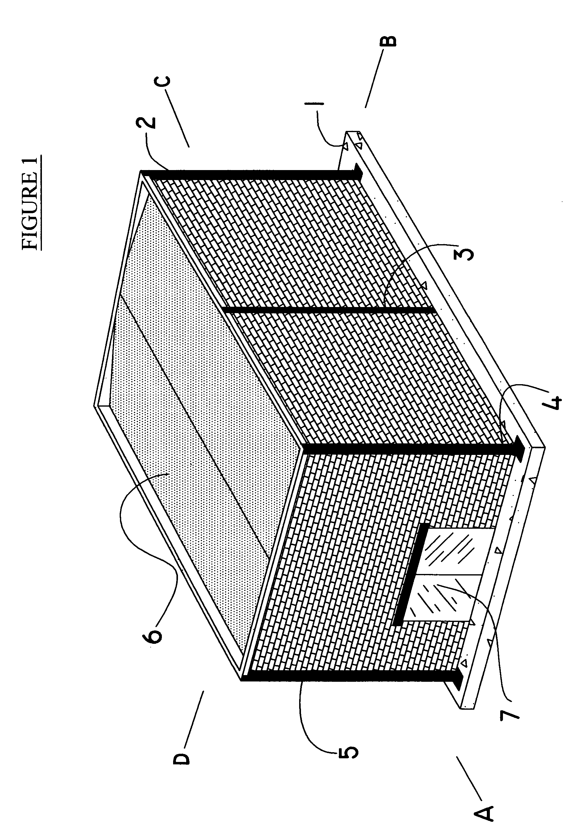
Static Descriptions of the Figures FIG. 1 is a diagrammatic perspective illustration of a typical building with steel and structural work. It is provided for general background and to assist the reader of the present invention with conceptualizing the patent. It is in no way to limit the patent's scope, only to provide an example for the application of the patent. The four sides of the building are labeled A, B, C, D, and components are labeled numerically one through seven. 1 represents the foundation for the building. 2, 3, 4, 5 are structural columns with an additional one not shown at the intersection of face C and D of the structure. Element 6 is the roof, and 7 is a typical door.
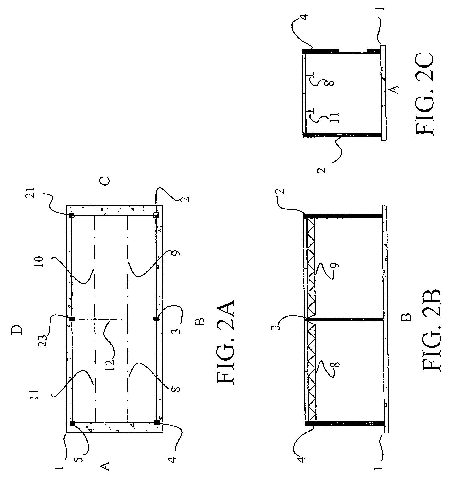
[0059]FIGS. 2A, 2B, and 2C illustrate a fragmentary plan view of the basic steelwork layout of the building shown in FIG. 1. FIG. 2 shows the alternating arrangement of the primary vertical columns, the secondary vertical columns, and roof and floor beams. The drawing has three views labeled FIGS. 2A, ...
PUM
Abstract
The present invention describes a fire stop system for wall board construction. The patent addresses the problem of a gap between the head of a wall and a metal fluted deck. Described here-in is a fire resistanceassembly made of multiple components of: a fire stop panel and a mounting channel. The fire stop panel or wall has a wallboard geometry manufactured to match the contour shape of a metal fluted deck in a “cookie cutter” fashion. This provides the advantages of saving time and material of wallboard construction, with a product that is novel, simple, and easy to manufacture and implement. The mounting channel of the fire stop system provides for an effective way to provide compliance of the stresses from the roofing / ceiling deck's stresses, easy assembly of the fire stop system, while allowing for a meeting of the fire safety rating.
Application Information
Patent Timeline
Application Date:The date an application was filed.
Publication Date:The date a patent or application was officially published.
First Publication Date:The earliest publication date of a patent with the same application number.
Issue Date:Publication date of the patent grant document.
PCT Entry Date:The Entry date of PCT National Phase.
Estimated Expiry Date:The statutory expiry date of a patent right according to the Patent Law, and it is the longest term of protection that the patent right can achieve without the termination of the patent right due to other reasons(Term extension factor has been taken into account ).
Invalid Date:Actual expiry date is based on effective date or publication date of legal transaction data of invalid patent.

