
System comprising heat-generator and cooler thereof, and disk array system

a technology of heat-generator and cooler, which is applied in the direction of insulated conductors, power cables, cables, etc., can solve the problems of increasing the complexity and cost of the disk array system, increasing the cost of the operation, and difficulty in removing the uneven temperature of a plurality of magnetic disk devices. , to achieve the effect of increasing the complexity and cost of the disk array system, and increasing the cost of the operation

Inactive Publication Date: 2010-08-17
NEC CORP
View PDF18 Cites 40 Cited by
  • Summary
  • Abstract
  • Description
  • Claims
  • Application Information

AI Technical Summary

Benefits of technology

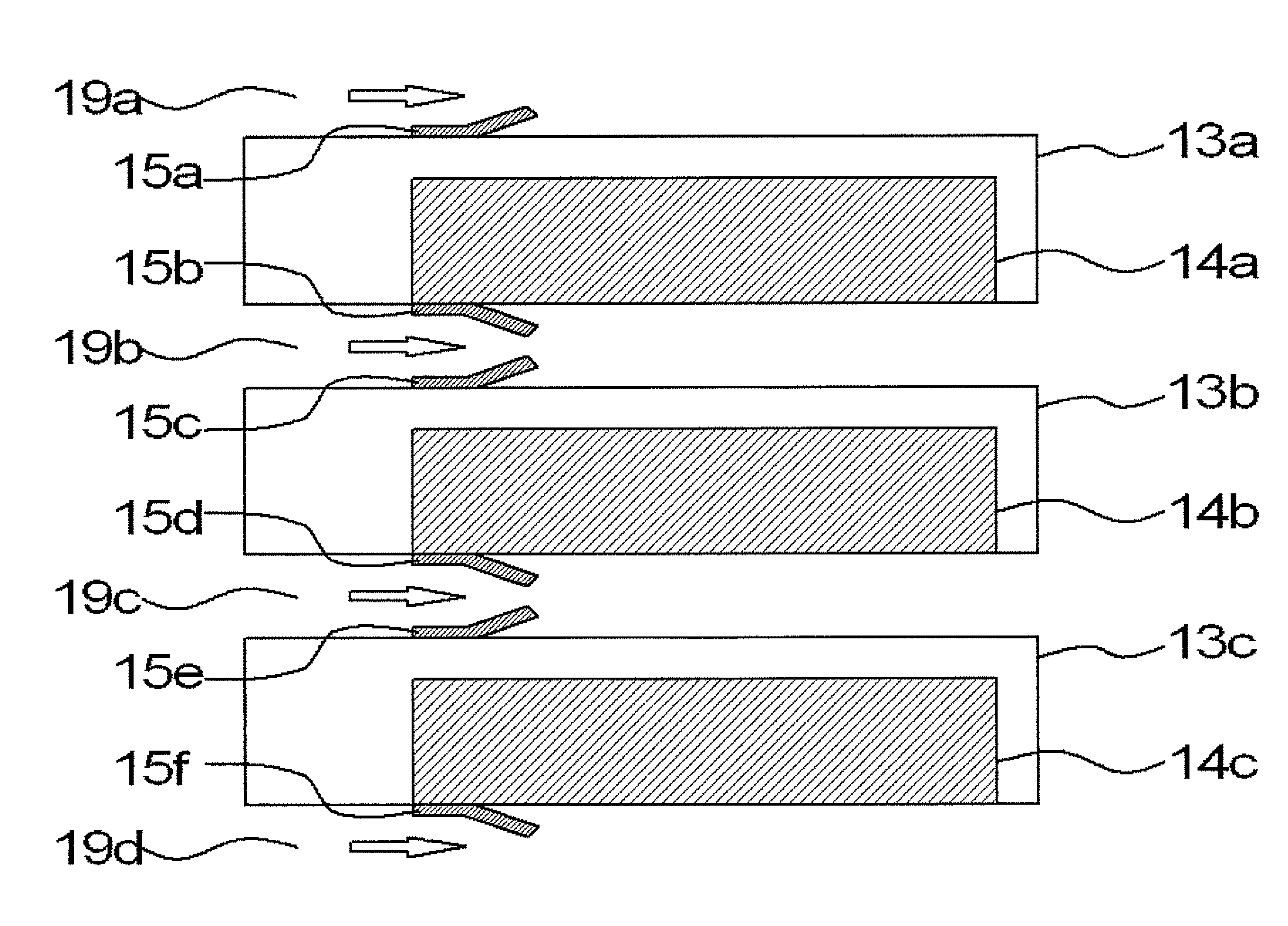
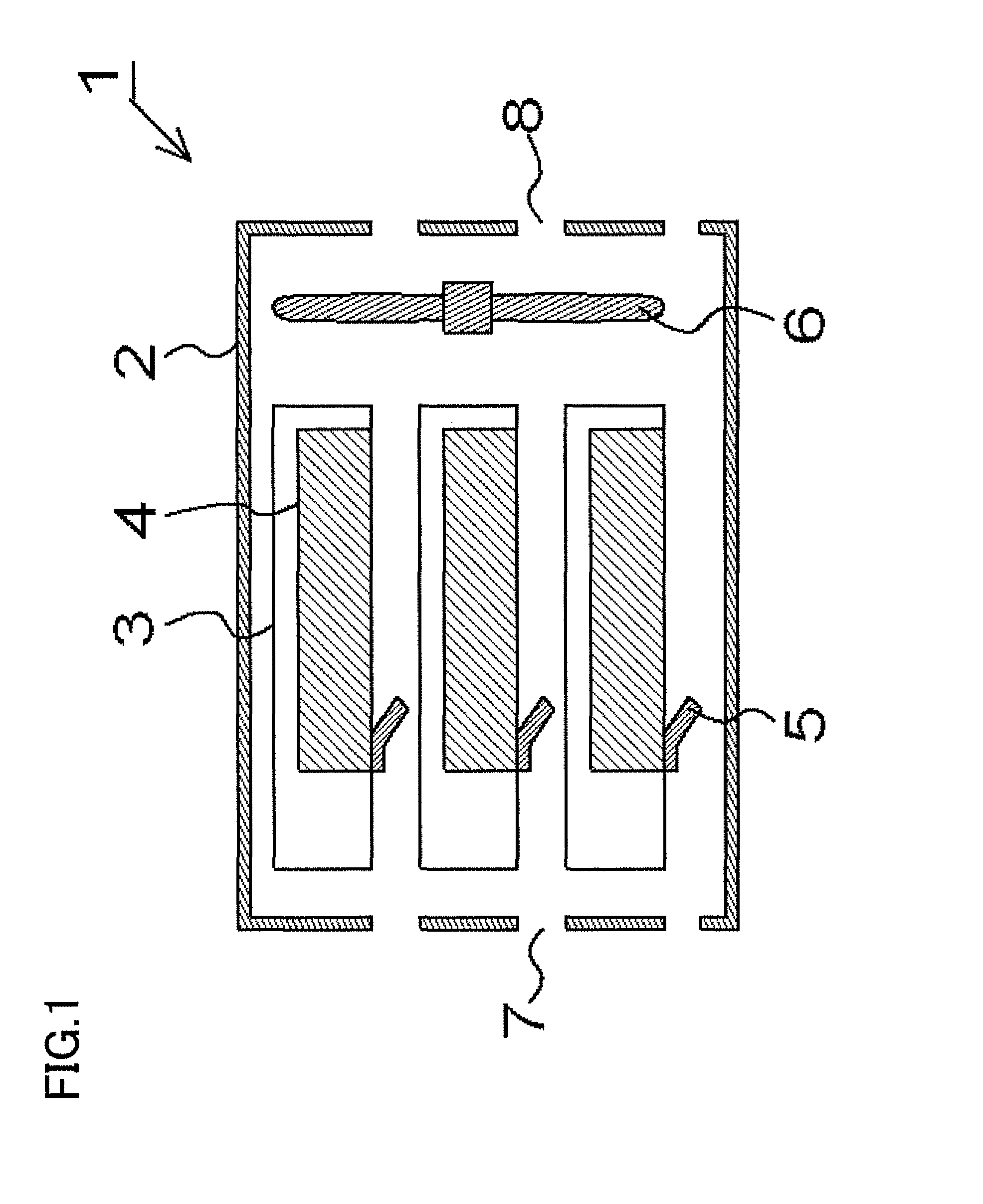
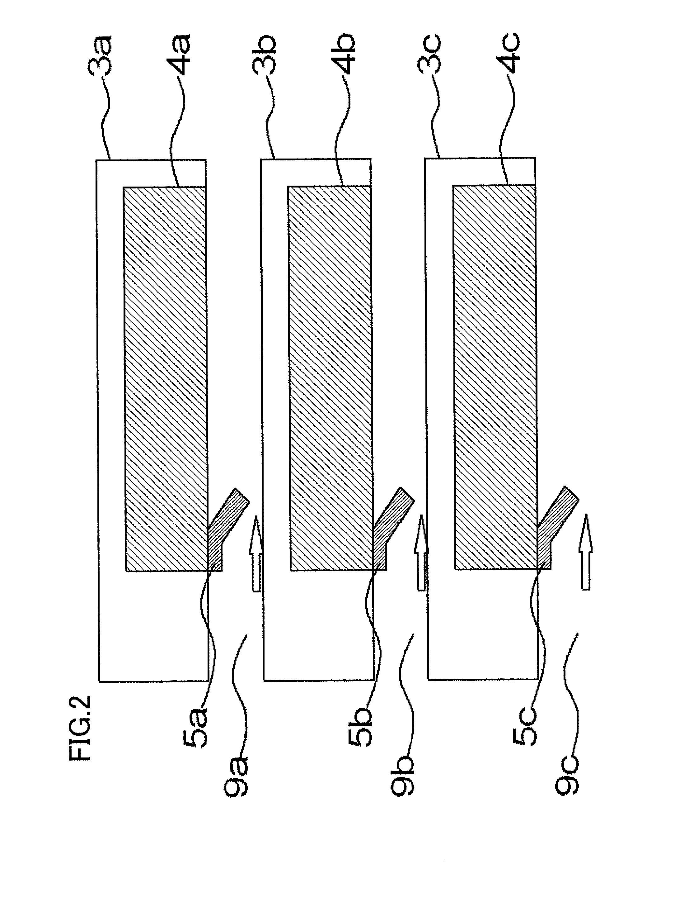
The present invention provides a system and a disk array system that can control the distribution of cooling power according to the state of heat generation in each heat-generator. The system includes multiple heat-generators, a cooling medium flow regulator that regulates the amount of cooling medium flow in response to the temperature of the heat-generators, and a cooling air flow regulator that regulates the amount of air flow to cool at least one of the heat-generators. The cooling power distribution can be controlled quickly and suitably based on the heat generation of each heat-generator, such as magnetic disk devices. This system helps to improve the cooling efficiency and reduce the complexity and cost of the disk array system.

Problems solved by technology

This causes problems that the disk array system becomes more complex and expensive and that the consumed power on the operation becomes greater.
If the number of the temperature sensors and fans relative to the number of the magnetic disk devices is reduced in order to avoid the problem, it is difficult to get rid of the unevenness of the temperature in a plurality of the magnetic disk devices.
Therefore, the shape memory alloys can not react to the change of the temperature of each printed board promptly.
There is also a possibility that the heat generated in the printed board may not be suitably transmitted to the shape memory alloy corresponding to the printed board since the air in the housing flows by the cooling fans.

Method used


Image

  • System comprising heat-generator and cooler thereof, and disk array system
  • System comprising heat-generator and cooler thereof, and disk array system
  • System comprising heat-generator and cooler thereof, and disk array system

Examples


Embodiment Construction

[0024]In the system according to the first aspect of the present invention, following preferred modes are presented.

[0025]The heat of the heat-generators may be transmitted to the cooling medium flow regulator directly or through a conductor.

[0026]Each heat-generator may have at least one cooling medium flow regulator, and the cooling medium flow regulator may regulate the amount of the flow of the cooling medium which is in contact with the heat-generator to which the cooling medium flow regulator is assigned.

[0027]The cooling medium flow regulator may comprise a flow regulating member that deforms in accordance to the heat of the heat-generator; particularly, it may be made up of a shape memory material.

[0028]In the disk array system according to the second aspect of the present inventions following preferred modes are presented.

[0029]Each magnetic disk device may have at least one air flow regulator.

[0030]The air flow regulator may regulate the amount of the flow of air for cooli...


PUM


Abstract

A system comprises: a plurality of heat-generators; at least one cooler that cools the heat-generators by letting a cooling medium flow; and at least one cooling medium flow regulator that regulates the amount of the flow of said cooling mediums in accordance to the heat of said heat-generators; wherein the heat of said heat-generators is transmitted to said cooling medium flow regulator without recourse to transmitting through said cooling medium or air. The system may be a disk array system.

Description

REFERENCE TO RELATED APPLICATION[0001]The present application is claiming the priority of the earlier Japanese patent application No. 2007-044059 filed on Feb. 23, 2007, the entire disclosure thereof being incorporated herein by reference thereto.FIELD OF THE INVENTION[0002]This invention relates to a system comprising a heat-generator and cooler thereof. The invention also relates to a disk array system comprising a plurality of magnetic disk devices as the heat-generator and a cooler thereof, for example.BACKGROUND OF THE INVENTION[0003]A system having a heat-generator such as an electrical device or electronic device often comprises a cooler to cool a heat-generator. A disk array system comprising a plurality of magnetic disk devices as the heat-generator is given as an example.[0004]The disk array system has a plurality of the magnetic disk devices for reliability and fast processing or high capacity. The disk array system usually has a cooler such as a cooling fan to cool the m...

Claims


Application Information

Patent Timeline
Patent Type & Authority Patents(United States)
IPC IPC(8): H05K7/20
CPCG11B33/142G11B33/144H05K7/20145
Inventor UENO, HIDEHIRO
Owner NEC CORP
Learn More