System and method for implementing dynamic suppression and recreation of suppressed data in a communications environment

a technology of dynamic suppression and data, applied in the field of communication, can solve the problems of adding significant overhead and cost in order to accommodate a large number of end-users or data streams, many of the existing compression/suppression protocols are deficient, and achieving the effect of optimizing data exchange, eliminating or greatly reducing disadvantages and problems associated

Active Publication Date: 2010-08-17
CISCO TECH INC
View PDF17 Cites 0 Cited by
  • Summary
  • Abstract
  • Description
  • Claims
  • Application Information

AI Technical Summary

Benefits of technology

[0004]From the foregoing, it may be appreciated by those skilled in the art that a need has arisen for an improved suppression approach that optimizes data exchanges in a communications environment. In accordance with one embodiment of the present invention, a system and a method for providing protocols for dynamically suppressing data are provided that substantially eliminate or greatly reduce disadvantages and problems associated with conventional compression / suppression techniques.
[0006]Certain embodiments of the present invention may provide a number of technical advantages. For example, according to one embodiment of the present invention, a communications approach is provided that enhances bandwidth parameters for a given architecture. This is a result of the suppression scheme, which yields bandwidth gains by recognizing repetitious patterns. A given input bit stream may be identified as a candidate for suppression. Subsequently, the bit pattern is not transmitted over the backhaul, whereby the suppressed data can be simply played out or restored on the other end of the link.
[0007]Furthermore, the bandwidth savings can be produced without any increase in the complexity of multiplexing and demultiplexing schemes. Additionally, such an upgrade or enhancement may be provided to an existing system with minimal effort. A simple algorithm may be used to leverage infrastructure already in place. Thus, a complete system overhaul is not necessary. Such advantages may be particularly beneficial to service providers, as effective compression protocols significantly reduce their operating expenditures.
[0008]Note also that such an enhancement is flexible in that it can be extended to include a multitude of compressible, common, repetitive patterns. Thus, such a solution can be easily extended to signaling and packet data channels. This further allows such a configuration to accommodate a wide range of incoming flows, as it may be extended to a number of different types of traffic arrangements. Additionally, minimal overhead is incurred as a result of the operations of the present invention.

Problems solved by technology

Many architectures for effectuating proper data exchanges can add significant overhead and cost in order to accommodate a large number of end-users or data streams.
For example, a large number of T1 / E1 lines may be implemented to accommodate heavy traffic, but such lines are generally expensive and, thus, usage of each one should be maximized (to the extent that it is possible) in order to achieve a system benefit per-unit of cost.
However, many of the existing compression / suppression protocols are deficient because they are static, unresponsive, and rigid.
Moreover, many such systems add overhead to the system, while not yielding a sufficient offsetting bandwidth gain.
Accordingly, the ability to provide a communications system that consumes few resources, optimizes bandwidth, and achieves minimal delay presents a significant challenge for network operators, service providers, and system administrators.

Method used


Image

  • System and method for implementing dynamic suppression and recreation of suppressed data in a communications environment
  • System and method for implementing dynamic suppression and recreation of suppressed data in a communications environment
  • System and method for implementing dynamic suppression and recreation of suppressed data in a communications environment

Examples


Embodiment Construction

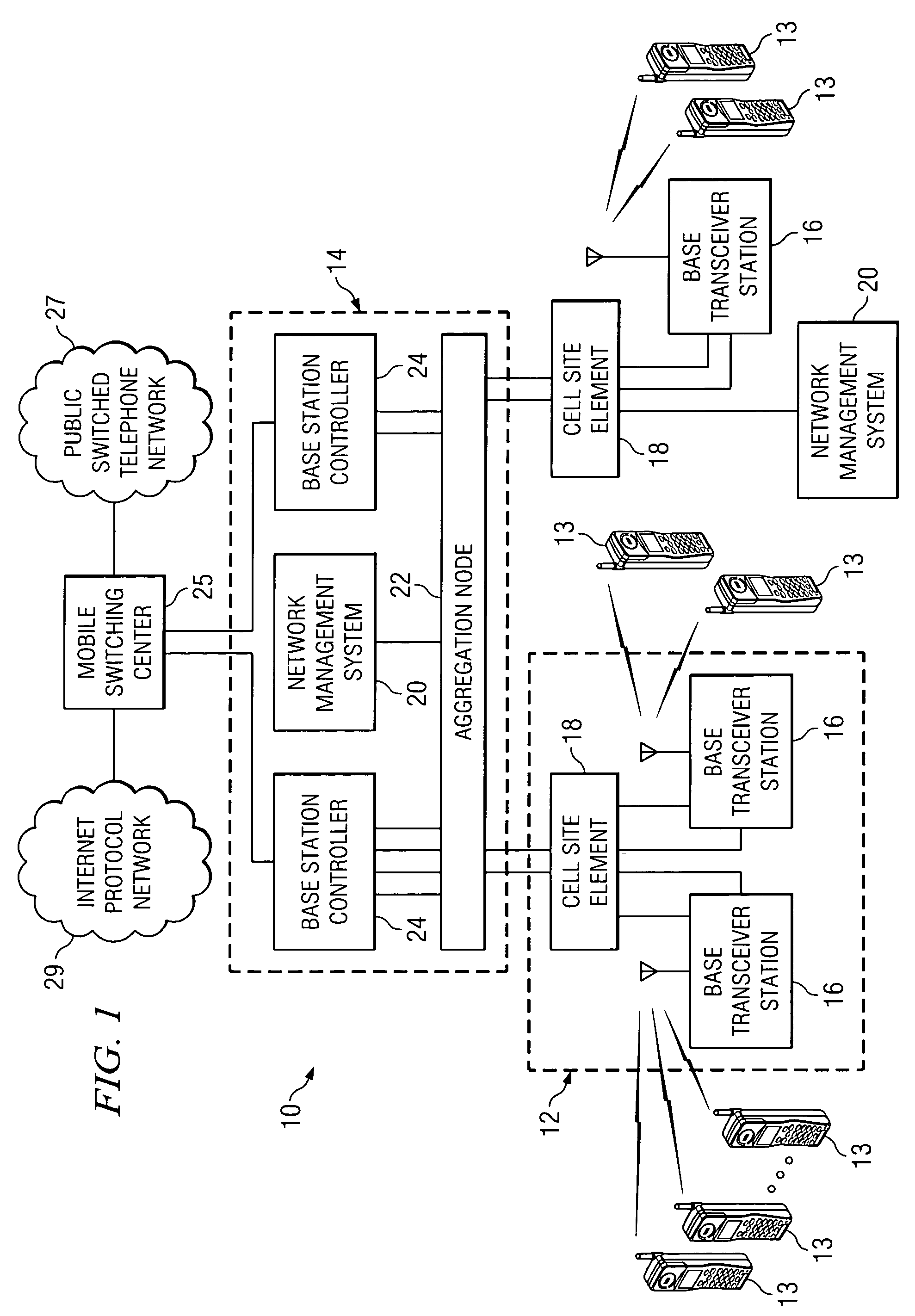
[0015]FIG. 1 is a simplified block diagram of a communication system 10 for suppressing data in a communications environment. Communication system 10 may include a plurality of cell sites 12, a plurality of mobile stations 13, a central office site 14, a plurality of base transceiver stations 16, a plurality of cell site elements 18, and a network management system 20. Additionally, communication system 10 may include an aggregation node 22, a plurality of base station controllers 24, a mobile switching center 25, a public switched telephone network (PSTN) 27, and an Internet protocol (IP) network 29. Note the communications links extending between cell site element 18 and aggregation node 22, as compared to the number of communication links extending between cell site element 18 and base transceiver stations 16. This arrangement has been provided in order to illustrate that without the present invention, the number of communication links between cell site 12 and central office site...


PUM


Abstract

A method for communicating data is provided that includes receiving a plurality of bits associated with a communications flow and determining whether one or more samples included in the flow should be suppressed. The method also includes suppressing a selected one or more of the samples if the selected samples are similar to previously received samples. In a more particular embodiment, the method also includes positioning unique samples that are included in the flow in a super-frame to be communicated to a next destination. Additionally, the method may include receiving the unique samples and evaluating the unique samples in order to restore a plurality of bits associated with the communications flow.

Description

TECHNICAL FIELD OF THE INVENTION[0001]The present invention relates in general to the field of communications and, more particularly, to a system and a method for implementing dynamic suppression in and recreation of suppressed data a communications environment.BACKGROUND OF THE INVENTION[0002]Communication systems and architectures have become increasingly important in today's society. One aspect of communications relates to maximizing bandwidth and minimizing delays associated with data and information exchanges. Many architectures for effectuating proper data exchanges can add significant overhead and cost in order to accommodate a large number of end-users or data streams. For example, a large number of T1 / E1 lines may be implemented to accommodate heavy traffic, but such lines are generally expensive and, thus, usage of each one should be maximized (to the extent that it is possible) in order to achieve a system benefit per-unit of cost.[0003]Compression techniques can be used ...

Claims


Application Information

Patent Timeline
Patent Type & Authority Patents(United States)
IPC IPC(8): H04J3/18
CPCH04W28/06H04W88/08
Inventor BALES, SCOTT A.BORDONARO, FRANK G.FUSSELL, JOHN P.PEARCE, BERNIE P.SELLENTIN, UWESCHMIDT, PAUL A.
Owner CISCO TECH INC
Why Eureka
Try Eureka