
Creep tester for precision load control with weight

a load control and tester technology, applied in the field ofcreep testers, can solve the problems of inability to achieve complete sealing and inability to continuously apply precise load to test concrete samples

Active Publication Date: 2010-08-31
KOREA ELECTRIC POWER CORP
View PDF40 Cites 7 Cited by
  • Summary
  • Abstract
  • Description
  • Claims
  • Application Information

AI Technical Summary

Problems solved by technology

However, since it is impossible to achieve complete sealing due to characteristics of hydraulic pressure, the hydraulic pressure actuator requires periodic supplementation of hydraulic pressure to have a constant hydraulic pressure during operation.
However, since such a manual operation or a separate electrical device is also operated based on detection of sensors in a predetermined range of hydraulic pressure, they have a problem in that a precise load cannot be continuously applied to test concrete samples.

Method used


Image

  • Creep tester for precision load control with weight
  • Creep tester for precision load control with weight
  • Creep tester for precision load control with weight

Examples


Embodiment Construction

[0015]Exemplary embodiments of the present invention are described in detail with reference to the appended Figures. Like reference numerals denote like elements throughout the drawings.

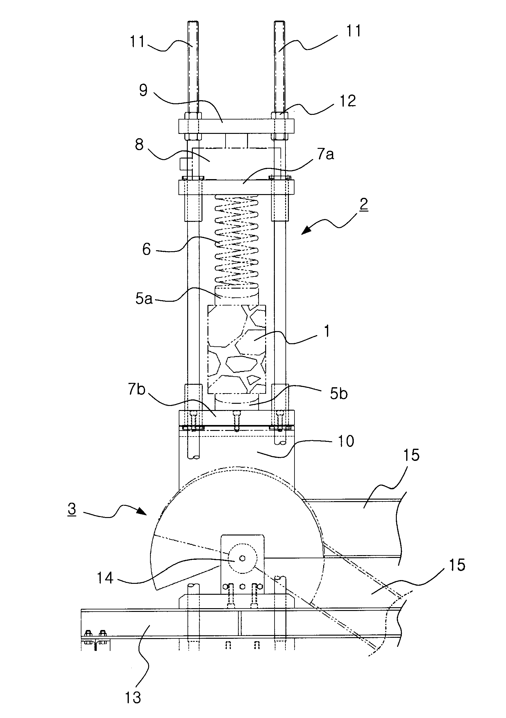
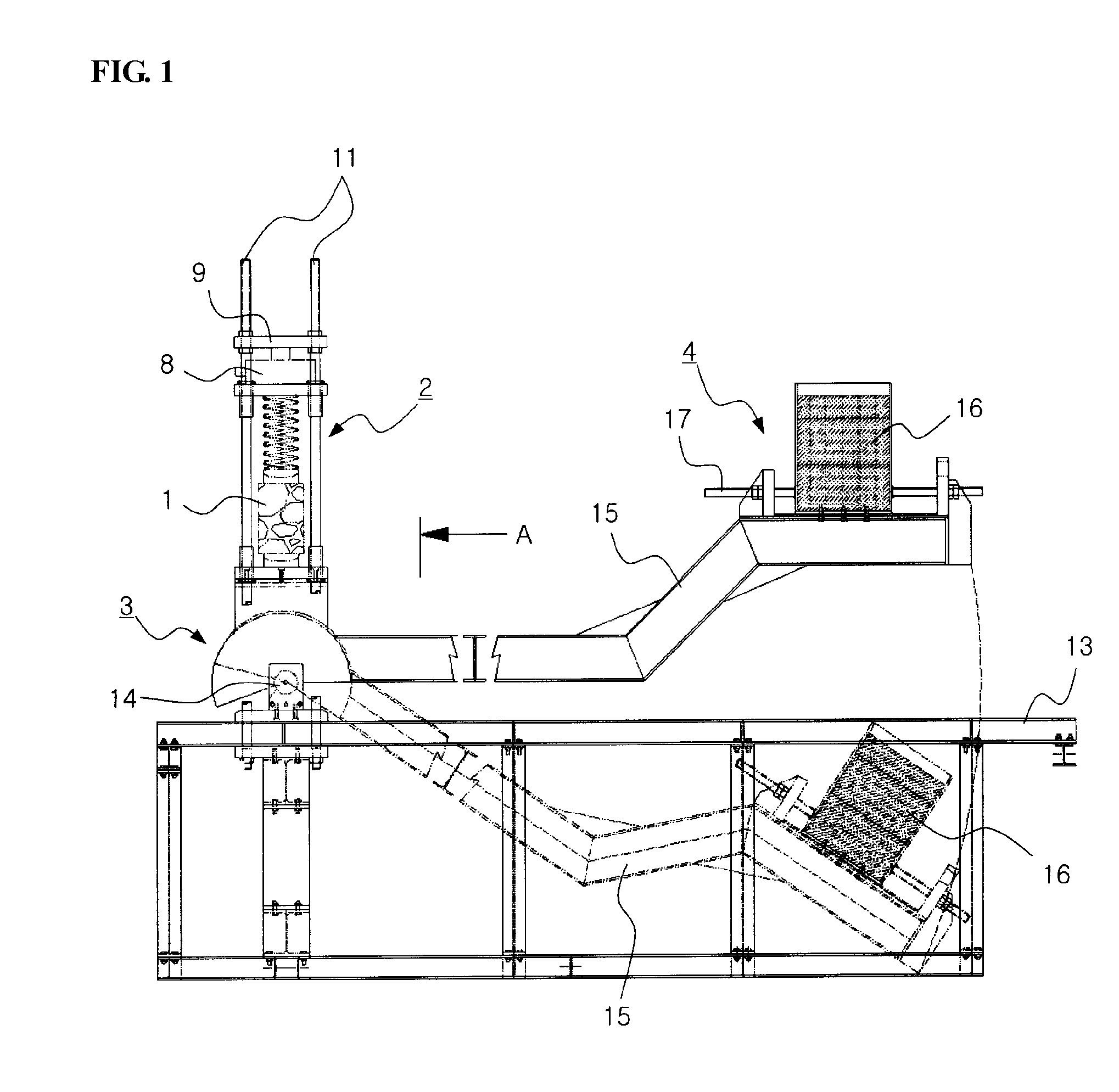
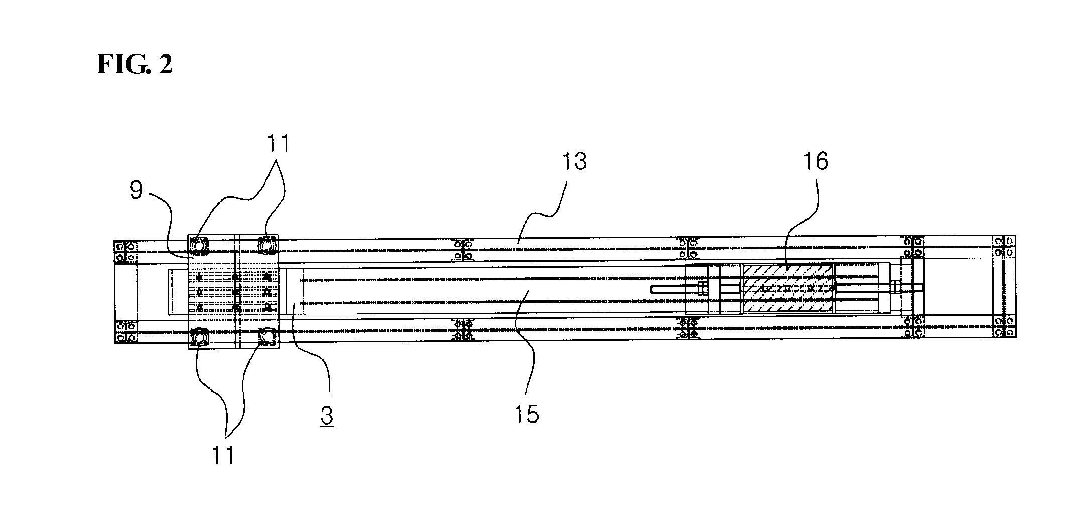
[0016]FIG. 1 is a front view of a creep tester for precise load control with a self load according to an exemplary embodiment of the present invention, FIG. 2 is a plan view of the creep tester illustrated in FIG. 1, FIG. 3 is a side view taken in the direction of arrow A in FIG. 1, and FIGS. 4 and 5 are partially enlarged views of FIGS. 1 and 3.

[0017]Referring to FIG. 1, the creep tester according to this example embodiment is configured to measure creep characteristics of construction material such as a concrete specimen 1. The creep tester includes a movable actuator 2 capable of loading corresponding to change in length of the concrete specimen 1, a cam actuator 3 operated in association with the movable actuator 2, and a self weight actuator 4.

[0018]The movable actuator 2 includes upper and lowe...


PUM

PropertyMeasurementUnit
creep testeraaaaaaaaaa
creepaaaaaaaaaa
lengthaaaaaaaaaa

Abstract

A creep tester for a precise and accurate creep test includes a movable actuator capable of loading corresponding to change in length of a specimen, a cam actuator operated in association with the movable actuator, and a self weight actuator. The movable actuator includes upper and lower spherical adjusting seats to hold upper and lower portions of the specimen, a spring disposed on the upper spherical adjusting seat to correspond to a minute deformation of the specimen, upper and lower movable tables respectively contacting the spring and the lower spherical adjusting seat, a load cell and a stationary table disposed on the upper movable table, and a movable loading table disposed below the lower movable table to apply a predetermined load to the specimen. The creep tester can perform a precise creep test by continuously applying a constant load without supplementation of hydraulic pressure.

Description

CROSS-REFERENCE TO RELATED APPLICATIONS[0001]The present application claims priority to Application No. 10-2007-0066411, filed in the Republic of Korea on Jul. 3, 2007, which is expressly incorporated herein in its entirety by reference thereto.FIELD OF THE INVENTION[0002]The present invention relates to a creep tester for a precise and accurate creep test in structural testing of concrete and other construction materials, and more particularly to a creep tester for precision load control with self weight, which can perform a precise creep test by continuously applying a semi-permanently constant load without supplementation of hydraulic pressure by external electrical means or manual operations.BACKGROUND INFORMATION[0003]Storage buildings of nuclear power plants are generally constructed by a post-tensioning construction method to obtain structural reinforcement. In the post-tensioning construction method, a load is applied based on a design value of an initial tensioning amount, ...

Claims


Application Information

Patent Timeline
Patent Type & Authority Patents(United States)
IPC IPC(8): G01N3/02G01N3/08G01N11/00
CPCG01N3/10G01N2203/0071G01N3/02G01N3/00
Inventor PARK, DONG SU
Owner KOREA ELECTRIC POWER CORP
Learn More