Floating dock structure

a dock and structure technology, applied in dry docking, floating buildings, marine site engineering, etc., can solve the problems of torquing force in the connecting structure between the side rails of the dock, damage to the framework and the connection to the floatation casing, and the known floating dock, so as to eliminate noise and wear, and facilitate assembly and repair.

Inactive Publication Date: 2010-08-31
MANUFACTURIERS TECHNOMARINE INC TECHNOMARINE MFG
View PDF7 Cites 11 Cited by
  • Summary
  • Abstract
  • Description
  • Claims
  • Application Information

AI Technical Summary

Benefits of technology

[0009]Another feature of the present invention is to provide a floating dock structure having a concrete slab decking which is supported on connectors which isolate the concrete slabs from contact with the metal support members of the dock structure to eliminate noise and wear and permit ease of assembly and repair and provide access to the space under the floor.

Problems solved by technology

However, there are several problems associated with such known floating docks.
One such problem is the torquing force in the connecting structure between the side rails of the dock when the dock is subjected to large wave action or impact forces imparted to the dock by large yachts when docking or during severe weather conditions.
The torquing forces imparted in the framework interconnecting the side rails will often cause damage to the framework and the connection to floatation casings secured.
It is not easy to repair docks because of the many watercrafts that are docked.
Another disadvantage of such docks is that they do not provide sufficient space underneath the floor structure for the passages of large conduits which are required to provide proper service to larger yachts, such as megayachts, wherein piping of four to five inches (4 to 5 inches) in outer diameter is required.
However, the contact between the concrete slabs and the metal support stringers make the dock noisy during displacement by wave action wherein the concrete slabs are frictionally displaced in contact with the metal stringers.
Another disadvantage is that because of this friction and the fact that the concrete is in contact with salt water or fresh water, the concrete deteriorates at the friction areas and this causes deterioration of the slabs and damages the support surfaces of the stringers.
A still further disadvantage is that many of these metal docks have their side rails, cross-members and stringers constructed of several parts which may be attached together by bolt fasteners or by welding.
The bolt fasteners become loose with time due to the torquing action of the frame and require to be re-tightened.
If the parts are welded together, this makes the dock more costly to fabricate and the many welds may be subject to breakage, particularly with members subjected to torquing force.

Method used


Image

  • Floating dock structure
  • Floating dock structure
  • Floating dock structure

Examples


Embodiment Construction

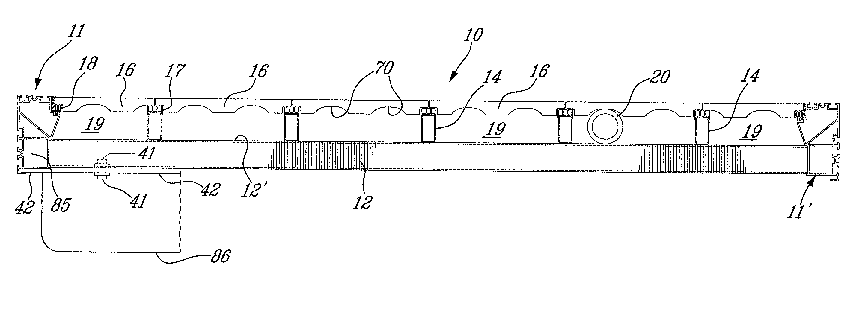
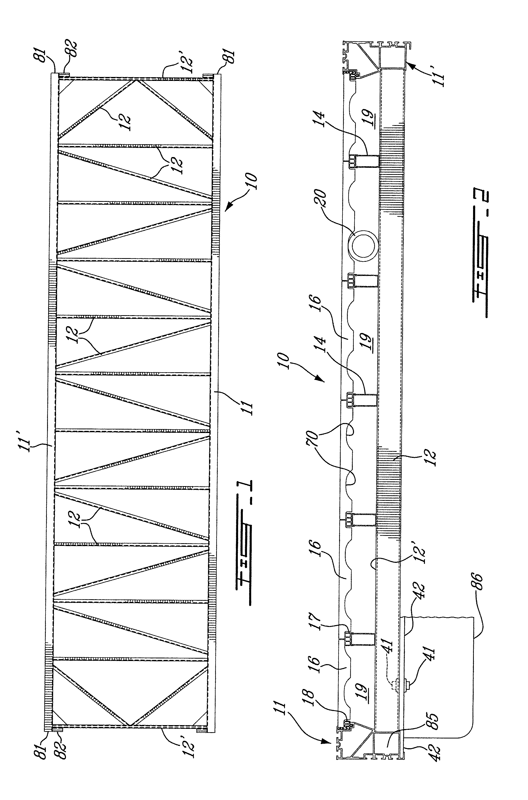
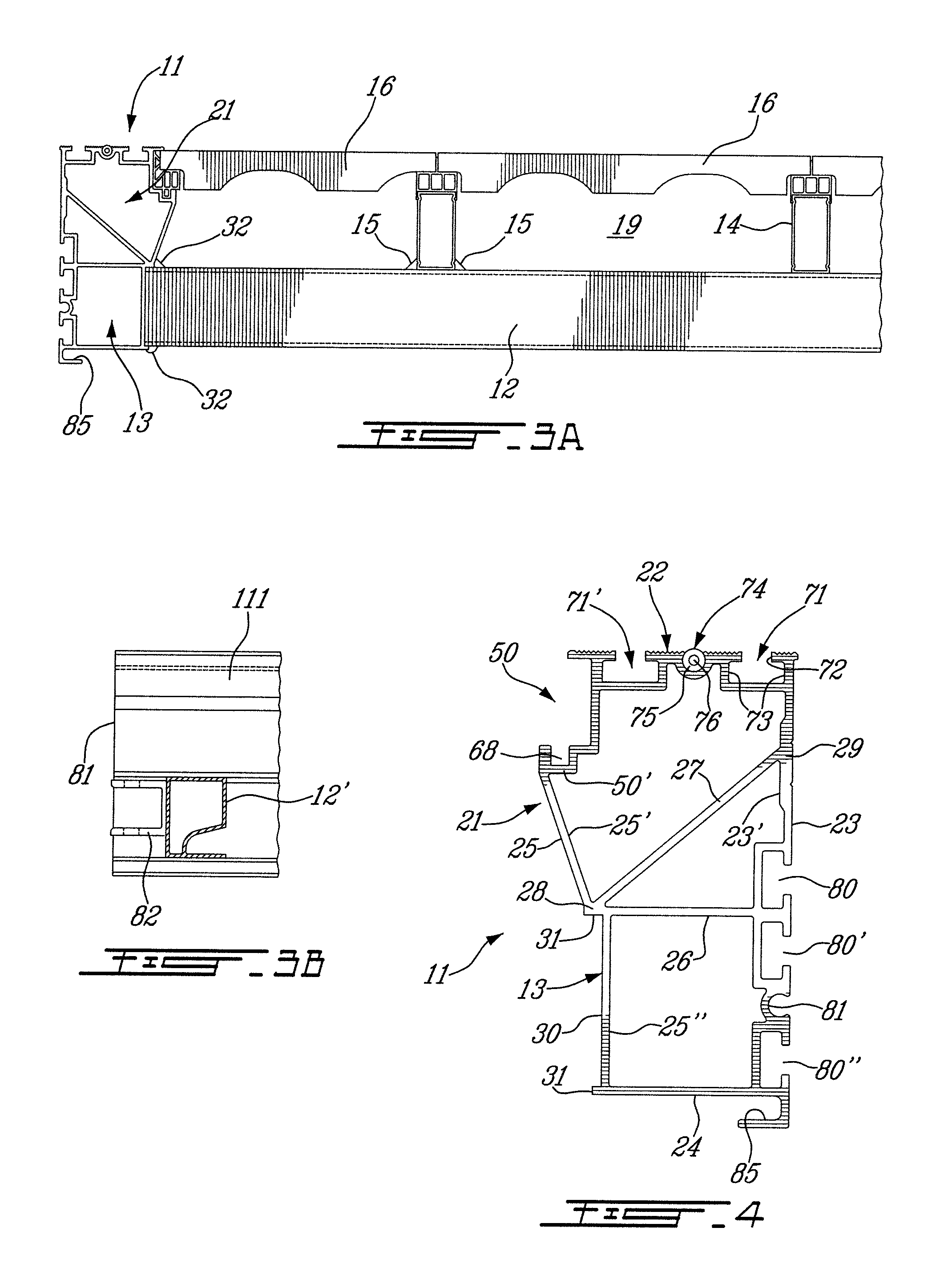
[0029]Referring now to the drawings and more particularly to FIGS. 1 and 2, there is shown generally at 10 the floating dock structure of the present invention. The floating dock structure is a metal structure and is comprised of a pair of aluminum extruded, one-piece, side rails 11 and 11′ which are secured together in spaced-apart substantially parallel relationship by a plurality of cross-members 12. The cross-members 12 are also aluminum extruded one-piece members and they are secured to a lower tubular portion 13 of the side rails 11 by welding. A plurality of elongated deck support stringers 14 are secured in spaced-apart parallel relationship on a top wall 12′ of the cross-members 12 by welding as shown at 15 in FIG. 3A. Decking floor members 16; hereinshown in the form of concrete tiles, are supported between the side rails 11 and 11′ by the stringers 14 and more specifically on decking support connectors 17 removably secured to the top end of the deck support stringers 14 a...


PUM


Abstract

A floating dock structure is comprised of a pair of single-piece side rails secured together in spaced-apart substantially parallel relationship by a plurality of single-piece cross-members connected between the side rails to a lower tubular portion thereof. The side rails are hollow, tubular aluminum extruded side rails defining a top wall, an exterior side wall, a bottom wall and an interior side wall spaced inwardly from the exterior side wall. Elongated deck support stringers are secured in spaced-apart relationship on a top wall of the cross-members. Decking floor members are supported by the deck support stringers elevated from the top face of the cross-members a distance of up to about five inches (5 inches) to create underfloor passages adapted for the passage of conduits and services material. Floatation support casings are secured under the cross-members.

Description

TECHNICAL FIELD[0001]The present invention relates to a floating dock structure having a pair of aluminum extruded hollow side rails and cross-members which are secured to a lower tubular portion of the side rails and extending therebetween to provide a metal dock structure which is highly resistant to impact loads and torquing forces and which provides improved underfloor space for the passage of service conduits and material.BACKGROUND ART[0002]Docks formed from aluminum extrusions and metal trusses and beams are known in the art. However, there are several problems associated with such known floating docks. One such problem is the torquing force in the connecting structure between the side rails of the dock when the dock is subjected to large wave action or impact forces imparted to the dock by large yachts when docking or during severe weather conditions. The torquing forces imparted in the framework interconnecting the side rails will often cause damage to the framework and the...

Claims


Application Information

Patent Timeline
Patent Type & Authority Patents(United States)
IPC IPC(8): B63B35/44E02B3/00
CPCB63C1/02
Inventor BIGLER, OLIVIERBARBEAU, CLAUDE
Owner MANUFACTURIERS TECHNOMARINE INC TECHNOMARINE MFG
Why Eureka
Try Eureka