
Clip-attachable light strings for Christmas tree branches

a clip-attachable, tree branch technology, applied in free standing, lighting and heating equipment, support devices for lights, etc., can solve problems such as not focusing

Inactive Publication Date: 2010-08-31
RAWLINGS APRIL
View PDF15 Cites 39 Cited by
  • Summary
  • Abstract
  • Description
  • Claims
  • Application Information

AI Technical Summary

Benefits of technology

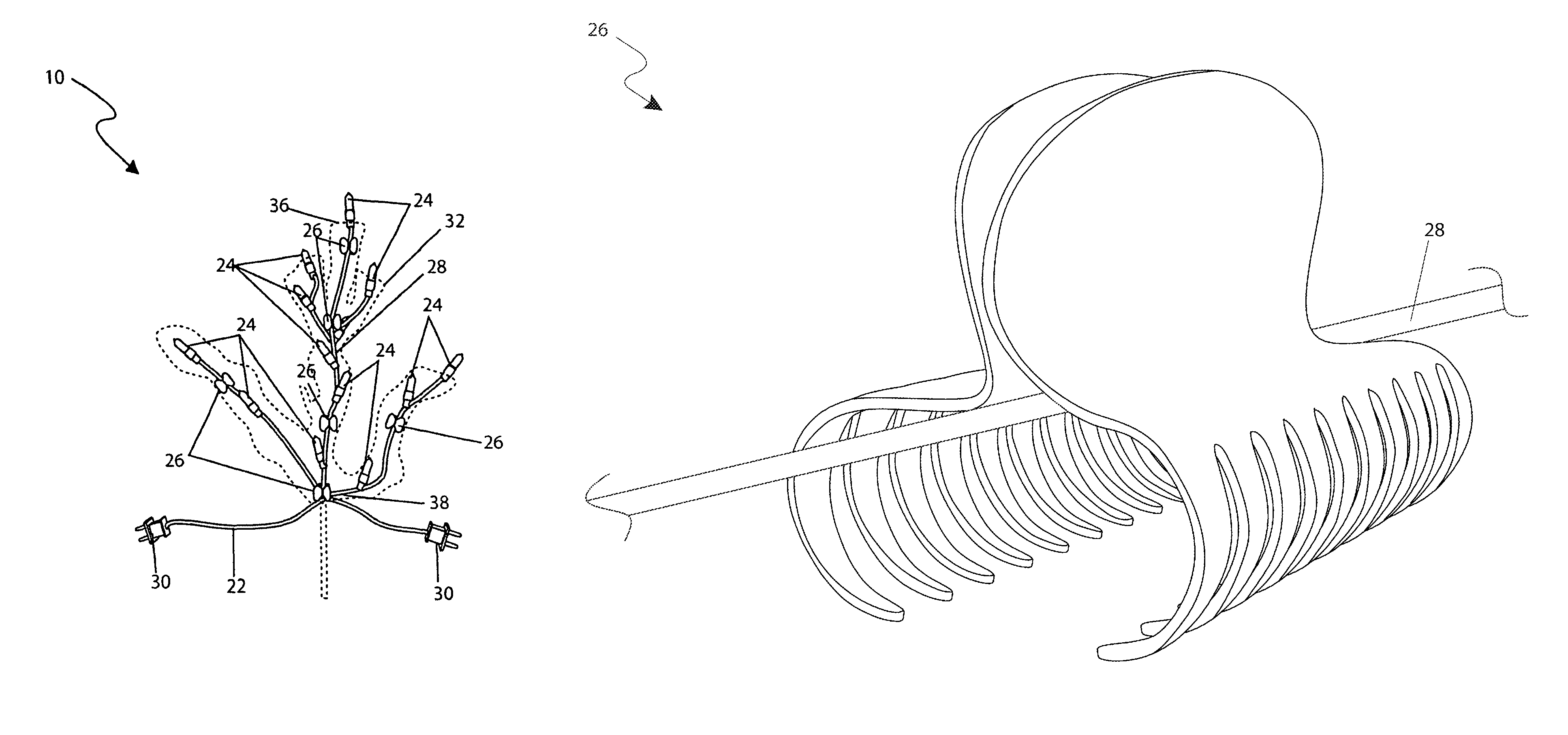
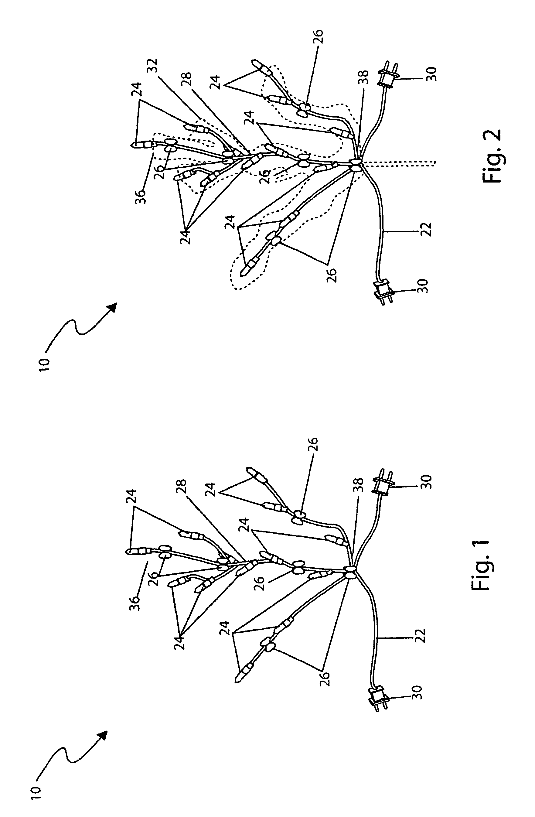
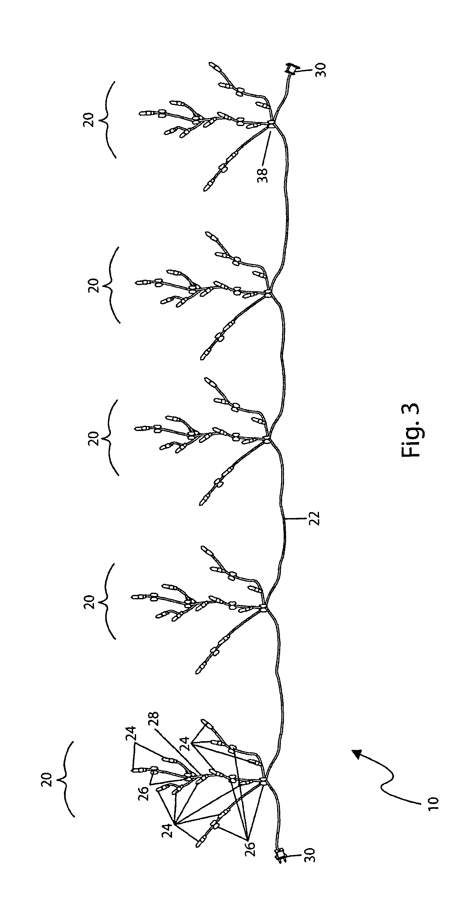
"The present invention provides an attachable light string device for tree branches that uses at least two clip attachment means to secure individual light strands to the outline of each tree branch in a more realistic manner. The device includes a central bus wire, a plurality of individual light strands with light bulbs arranged to outline the tree branches, and at least one clip attachment means to secure each light strand to the tree branch. The device can decorate all types of trees by interconnecting as many light string devices as needed. The clip attachment means comprise a claw-like clip or similar clip and can be located at the outer or inner end of each individual light strand. The device can have a variety of light bulbs, such as LEDs, special effect lights, or flashing lights, and can be available in different shapes, sizes, and colors. The electrical plug can be a male and female electrical plug or a wall outlet. The individual light strands can also have a vertical light bulb located at the outer end where an ornament can be placed and illuminated. The method for using the device is also provided."

Problems solved by technology

Lights are also used with Christmas trees, and while they add to the aesthetic quality of the tree, especially at night, they only cover the surface perimeter of the tree and do not emphasize the true beauty of each branch or bough.
Additionally, daylight hours reveal the wiring that loops around the circumference of the tree which sticks out like a sore thumb in an unsightly manner.

Method used


Image

  • Clip-attachable light strings for Christmas tree branches
  • Clip-attachable light strings for Christmas tree branches
  • Clip-attachable light strings for Christmas tree branches

Examples


Embodiment Construction

[0044]The best mode for carrying out the invention is presented in terms of its preferred embodiment, herein depicted within FIGS. 1 through 4. However, the invention is not limited to the described embodiment, and a person skilled in the art will appreciate that many other embodiments of the invention are possible without deviating from the basic concept of the invention and that any such work around will also fall under scope of this invention. It is envisioned that other styles and configurations of the present invention can be easily incorporated into the teachings of the present invention, and only one particular configuration shall be shown and described for purposes of clarity and disclosure and not by way of limitation of scope.

[0045]The terms “a” and “an” herein do not denote a limitation of quantity, but rather denote the presence of at least one of the referenced items.

[0046]The present invention describes a device and method for a clip-attachable light string for Christm...


PUM


Abstract

A decorative Christmas tree lighting system with individual light strands for each tree bough or branch is herein disclosed, comprising a central bus wire located near the trunk of the tree and a series of five (5) to ten (10) single-ended lighting strands originating in an outward or radial pattern therefrom the central bus wire. Each of these lighting “branch” strands has approximately ten (10) to twenty (20) individual light bulbs, depending on the overall size, and is routed along or around an individual branch or bough of the tree. Each individual light strand is held in place with at least two (2) clip means, one (1) near the outer end of the branch, and one (1) near the tree trunk, which help hold the lights in place. The central bus wire comprises a plurality of electrical plugs on each end to allow for end-to-end connection of multiple light systems. In such a manner, any size tree can be illuminated by simply adding additional light systems.

Description

RELATED APPLICATIONS[0001]The present invention was first described in a notarized Official Record of Invention on Oct. 16, 2007, that is on file at the offices of Montgomery Patent and Design, LLC, the entire disclosures of which are incorporated herein by reference.FIELD OF THE INVENTION[0002]The present invention relates generally to a decorative Christmas tree lighting system and, more particularly, to said lighting system comprising a central bus wire located near the trunk of the tree and a series of five (5) to ten (10) single-ended individual light strands originating in an outward or radial pattern therefrom the central bus wire, each individual light strand comprises approximately ten (10) to twenty (20) individual light bulbs and is routed along or around an individual branch or bough of the tree, and each individual light strand is held in place with at least two (2) clip means, one (1) near the outer end of the branch, and one (1) near the tree trunk.BACKGROUND OF THE I...

Claims


Application Information

Patent Timeline
Patent Type & Authority Patents(United States)
IPC IPC(8): F21V33/00
CPCF21S2/00F21S4/001F21V21/088F21W2121/04F21S4/10
Inventor RAWLINGS, APRIL
Owner RAWLINGS APRIL
Learn More