
Trailer stabilizing device and method of using same

a technology of stabilizing device and trailer, which is applied in the direction of vehicle maintenance, vehicle with living accommodation, transportation and packaging, etc. it can solve the problems of user discomfort, limited stroke length, and other known stabilizing devices, and achieve the effect of greater stability

Inactive Publication Date: 2010-09-07
HANSCOM PAUL
View PDF85 Cites 1 Cited by
  • Summary
  • Abstract
  • Description
  • Claims
  • Application Information

AI Technical Summary

Benefits of technology

[0006]The apparatus and method disclosed herein address these problems. The disclosed apparatus may be affixed at various locations at the bottom of a trailer and left attached when the trailer is being transported. The apparatus is relatively simple, and does not require crossed stabilizing bars. An embodiment of the apparatus comprises attachment brackets for the stabilizing bars which attachment brackets have selectively engaging lock mechanisms for restraining the stabilizing bar with respect to the attachment bracket. An embodiment of the apparatus may further comprise a modified base plate, to which stabilizing bars may be attached, to provide greater stability when the ground surface is uneven or unconsolidated. Yet another embodiment of the apparatus provides means for mechanically raising the drop leg of the landing gear and the attached base plate.
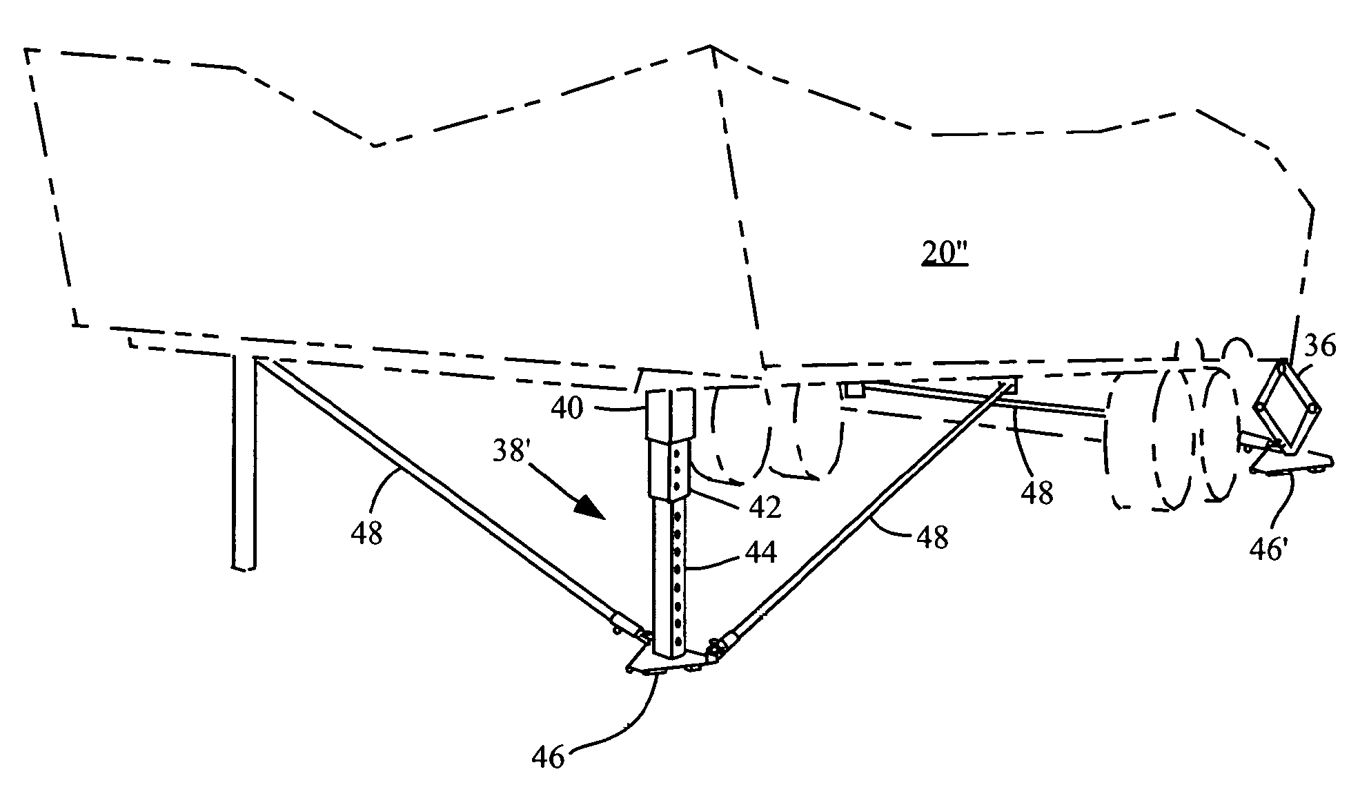
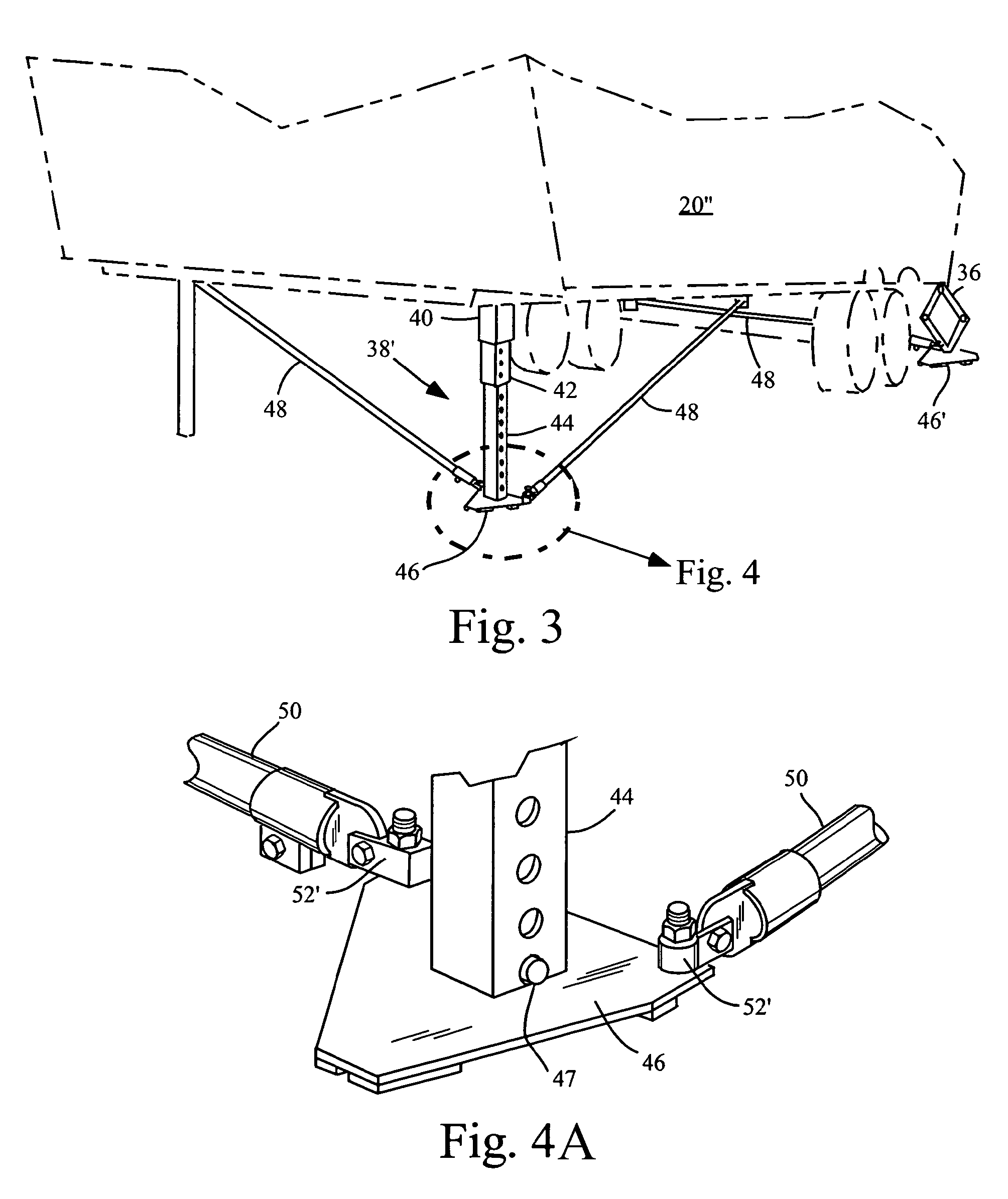
[0008]The disclosed apparatus further comprises a ground engaging base plate which is attached to the end of the adjustable length leg member. The ground engaging base plate comprises attachment means for one or more stabilizer members. The stabilizing member comprises a first end and a second end. The first end comprises means for attachment to the ground engaging base plate. The second end of the stabilizing member attaches to an attachment member which, in turn, is attached to the bottom of the trailer. The attachment member is adapted to slidably receive the second end of the stabilizing member, thereby allowing the effective length of the stabilizer to change.
[0009]The attachment member comprises locking means for engaging the stabilizing member and locking the stabilizing member with respect to the attachment member. The locking means allows the length of the stabilizing member disposed between the ground engaging base plate and the attachment member to be adjusted and locked as desired to increase the stability of the trailer. The locking means may be disengaged to allow the raising of the adjustable length leg member and the attached ground engaging base plate. It is to be appreciated that the straight-line distance between the ground engaging base plate and the attachment member is diminished as the ground engaging base plate is raised toward the bottom of the trailer. Therefore, the stabilizing member must slide with respect to the attachment member to allow the raising of the adjustable length leg member.

Problems solved by technology

Other known stabilizers are complicated, requiring crossing stabilizing bars or other elaborate supports.
However, because the stroke length may be limited, many of these devices comprise a drop tube member or extension which manually “drops” out of the lower member allowing additional length of the support leg, such that the end of the drop tube member reaches the ground.
Depending upon the ground conditions, the drop tube member or base plate may be muddy or dirty such that it is unpleasant for the user to place his or her hands about it to raise it.
In addition, depending upon the configuration of the trailer, the user may have to crouch or assume an uncomfortable position to lift the drop tube member back into the lower member.

Method used


Image

  • Trailer stabilizing device and method of using same
  • Trailer stabilizing device and method of using same
  • Trailer stabilizing device and method of using same

Examples


Embodiment Construction

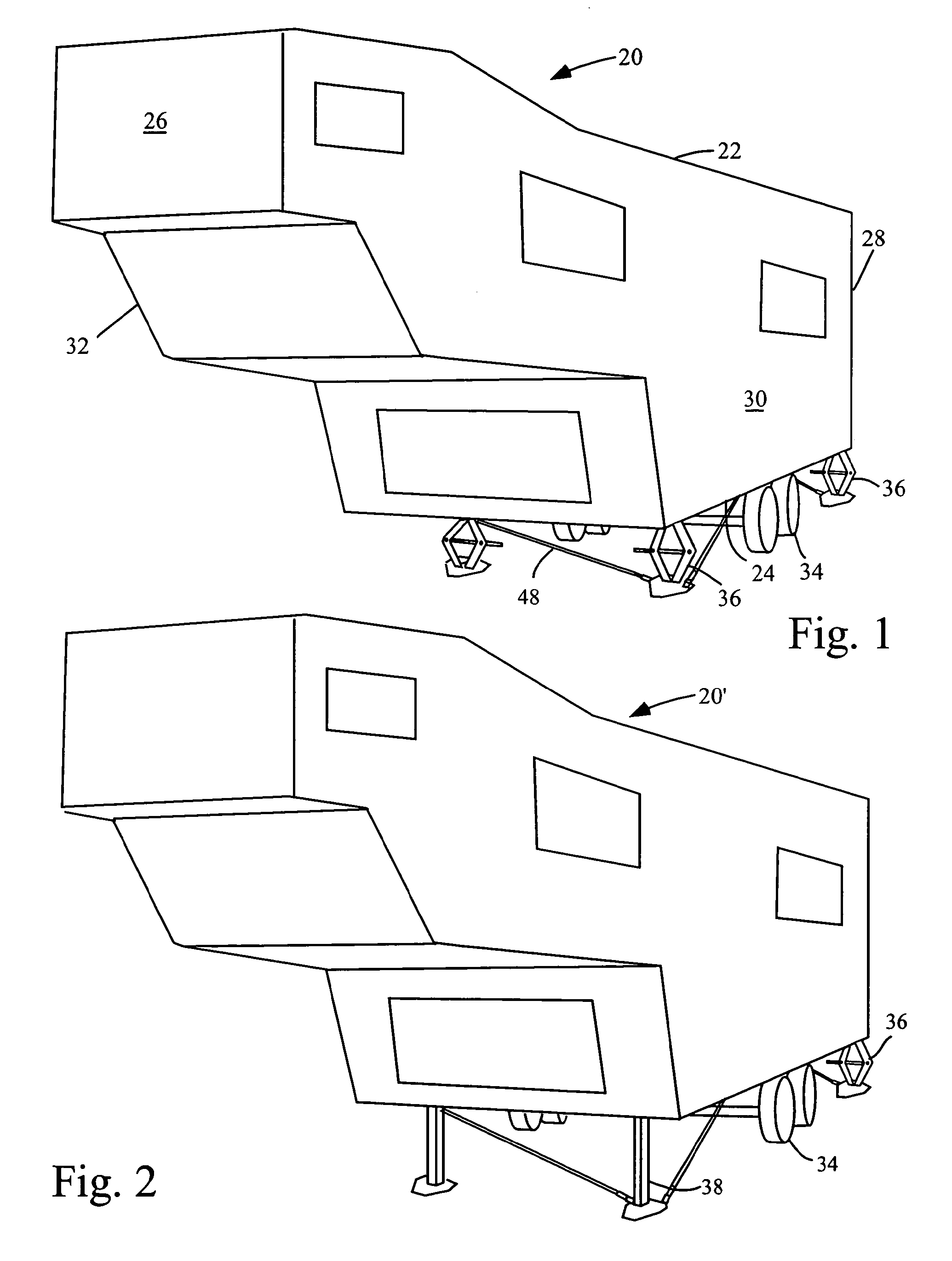
[0026]Referring now specifically to the drawings, FIG. 1 shows a schematic of a trailer 20 with an embodiment of the stabilizing device installed. The trailer 20 is of the type having a top 22 and a bottom 24 defining a vertical axis, a front 26 and a back 28 defining a longitudinal axis, a first side 30 and a second side 32 defining a transverse axis perpendicular to the longitudinal axis, and ground engaging wheels 34 attached to the bottom 24. As shown in FIG. 1, scissor jacks 36 may be a component of this embodiment. Many trailers 20 come pre-equipped with leveling mechanisms of various types, including scissor jacks 36, which are attached to the bottom 24 of the trailer 20. Other leveling mechanisms may include mechanically, hydraulically, pneumatically, and electrically actuated jacks. The leveling mechanisms are employed to bring the trailer to a relatively level orientation for the comfort of those inside. However, the leveling mechanisms are generally not sufficient on thei...


PUM


Abstract

An apparatus for stabilizing a stationary trailer comprises a adjustable length leg member, which may comprise the jack stands or landing gear which come as originally installed equipment on the trailer. Alternatively, the adjustable length leg members may comprise various types of jacks which are later attached to the bottom of the trailer. The apparatus further comprises a ground engaging base plate which is attached to the end of the adjustable length leg member. The ground engaging base plate comprises attachment means for one or more stabilizer members. The first end of the stabilizing member attaches to the ground engaging base plate and the second end of the stabilizing member attaches to an attachment member depending from the bottom of the trailer. The attachment member is adapted to slidably receive the second end of the stabilizing member. The attachment member comprises locking means for engaging the stabilizing member and locking the stabilizing member with respect to the attachment member. The locking means allows the length of the stabilizing member disposed between the ground engaging base plate and the attachment member to be adjusted and locked as desired to increase the stability of the trailer.

Description

CROSS-REFERENCE TO RELATED APPLICATION[0001]This is a continuation-in-part of U.S. application Ser. No. 10 / 899,921 filed on Jul. 26, 2004, for which the inventor claims domestic priority.BACKGROUND OF THE INVENTION[0002]The present invention generally relates to trailer stabilizing devices and more specifically to devices and methods which allow a person to stabilize a trailer with stabilizing members which allow the trailer to be transported without removal of the stabilizing members.[0003]A variety of different stabilizers are known for supporting stationary trailers, which stabilize the trailer and reduce movement of the trailer as people move within the trailer, thus making the trailer more comfortable for the occupants. Many of the known stabilizers must be installed after the trailer is set in place, requiring the positioning and installation of heavy pieces of equipment. Other known stabilizers are complicated, requiring crossing stabilizing bars or other elaborate supports. ...

Claims


Application Information

Patent Timeline
Patent Type & Authority Patents(United States)
IPC IPC(8): B60S9/04
CPCB60P3/36B60S9/06
Inventor HANSCOM, PAUL
Owner HANSCOM PAUL
Learn More