Card edge connector

a card edge and connector technology, applied in the direction of coupling device connection, coupling parts engagement/disengagement, electrical apparatus, etc., can solve the problems of affecting the operation of the whole system, affecting the function of the installed electric card, and affecting the stability of the system

Active Publication Date: 2010-09-07
MOLEX INC
View PDF4 Cites 23 Cited by
  • Summary
  • Abstract
  • Description
  • Claims
  • Application Information

AI Technical Summary

Benefits of technology

[0008]A card edge connector for receiving a card module is disclosed. The card edge connector can have two notches in two opposite side edges, respectively, and comprises an insulating housing including a receptacle provided with a plurality of terminals therein, for electrically and mechanically engaging with the card module, and a pair of support arms disposed at two opposite ends of the insulating housing, respectively, to form an accommodation space therebetween. The support arms can include a flexible portion having a distal free end, and the flexible portion can include a latch element extending from an upper edge of the flexible portion (which can be configured for establishing a latching engagement with a top surface of the card module while the card module is in the accommodation space). The support arm can also include a resistance provider (which can be disposed adjacent to the latch element and aligned vertically with the corresponding notch of the card module and can have an inclined surface which is inclined slightly inward and downward). The resistance provider can apply a relievable resistant upward force to an improperly inserted card module when the improperly inserted card module engages with the inclined surface while allowing the flexible portion to deflect if an unusually large force is applied to the inclined surface. Each support arm can also include and a lock element disposed in the corresponding notch, extending obliquely inward and upward from a lower edge of the flexible portion and configured to engage the corresponding notch thereof for preventing the card module from pulling out. The lock element can include a base portion that is configured for engaging a bottom corner edge of the notch. In operation, the base portion and the latch element can limit the vertical movement of the card module. In an embodiment, each support arm can comprise a flexible portion and a fixed portion placed below the flexible portion, with a latch element, a lock element disposed on the flexible portion and in the corresponding notch (configured for engaging the corresponding notch thereof for preventing the card module from pulling out), a securing element extending downward from a lower edge of the flexible portion and having a free end, and a confining element extending outward and then upward from a lower edge of the fixed portion to form a recess, wherein the free end of the securing element is confined within the recess.

Problems solved by technology

An incorrectly installed electric card may also not function properly and may even cause damage to the whole system.
The fixed stop element is normally very rigid and unmovable, and may cause damage to the card edge connector if an unusually large force is applied.
This serves to protect the elastic arm from overbending and, like the aforementioned fixed stop element, is also so rigid that damage to the card edge connector can occur.

Method used


Image

  • Card edge connector
  • Card edge connector
  • Card edge connector

Examples


Embodiment Construction

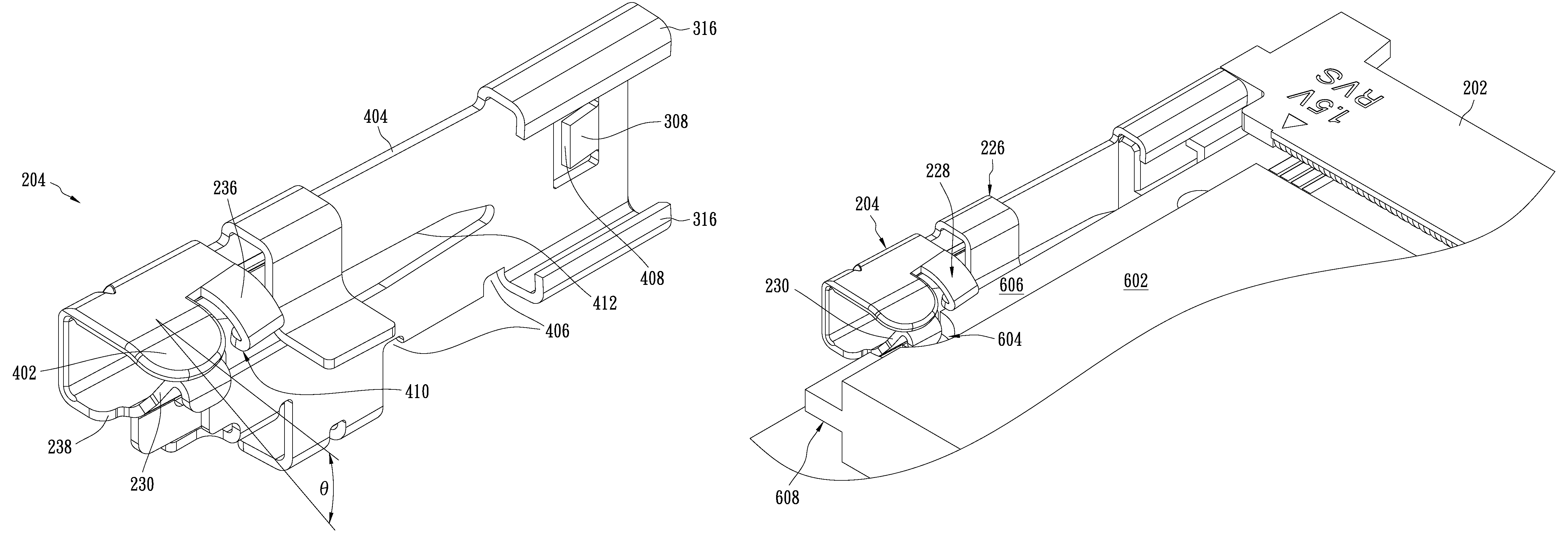
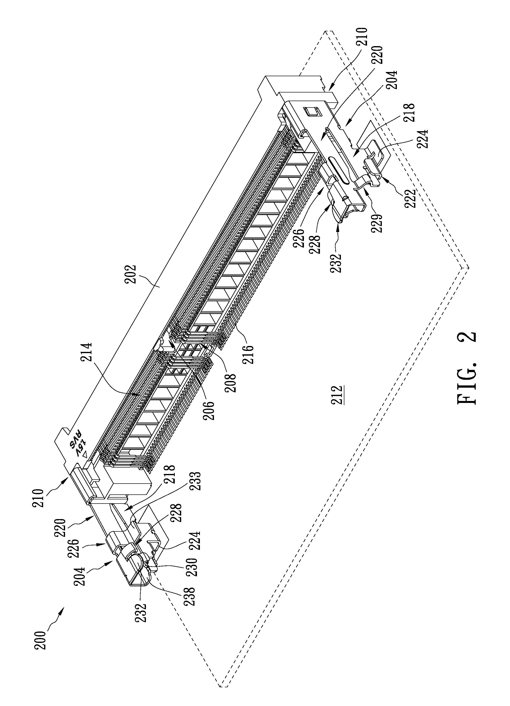
[0019]Referring to FIGS. 2-5, a card edge connector 200 in accordance with one embodiment comprises an elongated insulating housing 202 and a pair of support arms 204 disposed at two opposite ends 210 of the insulating housing 202. The support arms 204, extending horizontally along a printed circuit board 212, form an accommodation space for accommodating a card module (not shown) therebetween. The insulating housing 202 comprises an elongated receptacle 206, disposed therein along the elongated direction, used for adopting the card module (not shown). A plurality of terminals 208, 301 for electrically and mechanically engaging with the card module (not shown) are provided in pairs on the upper and lower inner surfaces of the receptacle 206 along the elongated direction. The card module (not shown) is electrically coupled to a printed circuit board 212 through the terminals 208, 301. Erected rectangular blocks 302, each of which has an indentation 304, are disposed at both ends of t...


PUM


Abstract

A card edge connector comprises an insulating housing comprising a receptacle provided with a plurality of terminals therein and a pair of support arms disposed at opposite ends of the insulating housing. Each of the support arms comprises a flexible portion having a distal free end. The flexible portion comprises a latch element configured for establishing a latching engagement with the card module and a resistance provider applying a relievable resistant upward force to an improperly inserted card module and causing the flexible portion to deflect while an unusually large force is applied thereto.

Description

RELATED CASES[0001]This application claims priority to Singapore Application No. 200807840-4 filed Oct. 21, 2008.BACKGROUND OF THE INVENTION[0002]The present invention relates to electrical connectors, and more particularly, to a card edge connector with a relievable resistance provider for preventing improper insertion.DESCRIPTION OF THE RELATED ART[0003]Many electronic apparatus can accept extension cards to extend their capability. For example, memory cards can be installed in computer systems to support large and memory-intensive scientific applications. To connect these extension cards to a printed circuit board, several types of connectors have been developed, and a card edge connector using latches for securing installed cards is one of the most common.[0004]U.S. patent publication no. 2007 / 0,270,011, entitled CARD EDGE CONNECTOR, filed May 8, 2007, by Yi-Tse Ho et al., for example, discloses a card edge connector allowing insertion of an electric card. The disclosed card edg...

Claims


Application Information

Patent Timeline
Patent Type & Authority Patents(United States)
IPC IPC(8): H01R13/62
CPCH01R13/6275H01R12/721
Inventor LEE, DAW WEI
Owner MOLEX INC
Why Eureka
Try Eureka