
MIMO antenna apparatus controlling number of streams and modulation and demodulation method

a technology of a mimo antenna and a stream, applied in the field of mimo antenna apparatus controlling the number of streams and the modulation and demodulation method, can solve the problems of increasing the cost, increasing the complexity of control, and difficult to mount a number of antenna elements on a small-sized apparatus with a size of one wavelength or less, and achieves a high signal quality communication and low transmission rate.

Active Publication Date: 2010-09-07
INVT SPE LLC
View PDF18 Cites 4 Cited by
  • Summary
  • Abstract
  • Description
  • Claims
  • Application Information

AI Technical Summary

Benefits of technology

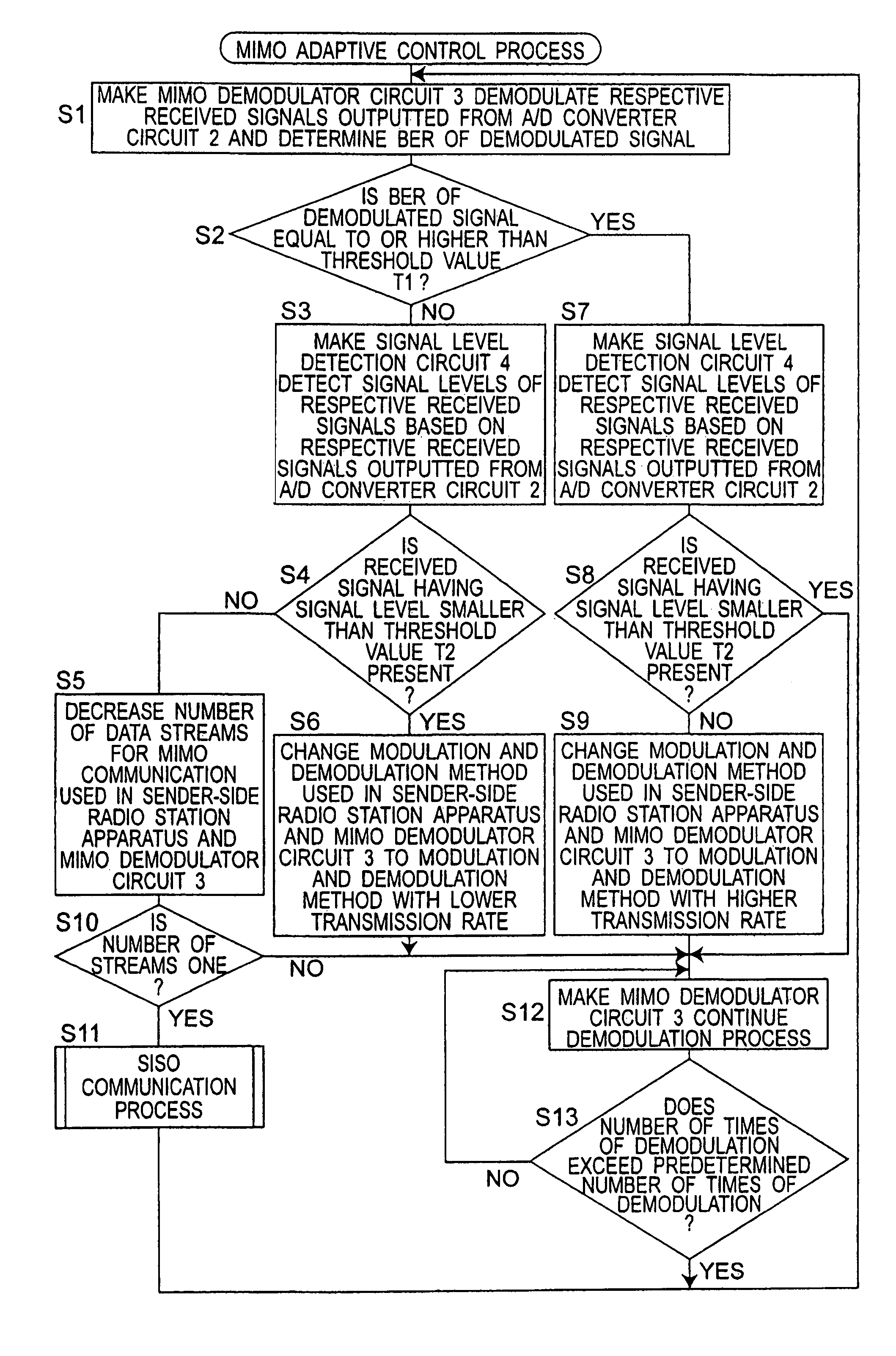
[0022]The advantageous effects derived from typical aspects of the invention disclosed in the present application will be briefly described as follows. In a MIMO radio communication incorporating the adaptive modulation, if the signal quality of the demodulated signal is equal to or lower than a threshold value, the respective received signal levels are obtained for the antenna elements constituting the MIMO antenna apparatus. If these received signal level are equal to or larger than a predetermined receiving power, the sender-side radio station apparatus is instructed to decrease the number M of transmitted data streams by one. When the number of data streams is decreased to one, the adaptive demodulation means may be used to control the amplitudes and phases of the plurality of received signals. Accordingly, a main beam of the MIMO antenna apparatus can be directed to a desired wave signal and nulls of the MIMO antenna apparatus can be directed to interference wave signals. If the signal quality of the demodulated signal is lower than the threshold value, the sender-side radio station apparatus is instructed to use a modulation and demodulation method with a lower transmission rate for data transmission. Thus, high-speed and high signal quality communication can be achieved through utilizing both of the high-speed radio transmission by the MIMO communication and the interference wave suppression technique using the adaptive array antenna.
derived from typical aspects of the invention disclosed in the present application will be briefly described as follows. In a MIMO radio communication incorporating the adaptive modulation, if the signal quality of the demodulated signal is equal to or lower than a threshold value, the respective received signal levels are obtained for the antenna elements constituting the MIMO antenna apparatus. If these received signal level are equal to or larger than a predetermined receiving power, the sender-side radio station apparatus is instructed to decrease the number M of transmitted data streams by one. When the number of data streams is decreased to one, the adaptive demodulation means may be used to control the amplitudes and phases of the plurality of received signals. Accordingly, a main beam of the MIMO antenna apparatus can be directed to a desired wave signal and nulls of the MIMO antenna apparatus can be directed to interference wave signals. If the signal quality of the demodulated signal is lower than the threshold value, the sender-side radio station apparatus is instructed to use a modulation and demodulation method with a lower transmission rate for data transmission. Thus, high-speed and high signal quality communication can be achieved through utilizing both of the high-speed radio transmission by the MIMO communication and the interference wave suppression technique using the adaptive array antenna.

Problems solved by technology

However, the prior art MIMO antenna apparatus of the first prior art document has the following problems.
However, since the MIMO antenna apparatus of the first prior art document has many transmitting antenna elements, it is quite difficult to mount a number of antenna elements on a small-sized apparatus with a size of one wavelength or less, such as a mobile telephone.
Moreover, even if the MIMO antenna apparatus of the first prior art document is employed at a base station of the mobile telephone system, the cost increases and the control becomes more complicated in response to an increase in the number of antenna elements.
Meanwhile, the prior art MIMO antenna apparatus of the second prior art document using the plurality of transversal filters has the following problems.
This prior art MIMO antenna apparatus can suppress the interference waves since the transversal filters are provided for the respective receiving antenna elements, however, the size of receiver circuit becomes disadvantageously larger.
In other words, it is impossible to configure this prior art MIMO antenna apparatus into a small-sized form, and to use this prior art MIMO antenna apparatus in a battery-operated mobile radio apparatus.

Method used


Image

  • MIMO antenna apparatus controlling number of streams and modulation and demodulation method
  • MIMO antenna apparatus controlling number of streams and modulation and demodulation method
  • MIMO antenna apparatus controlling number of streams and modulation and demodulation method

Examples


first preferred embodiment

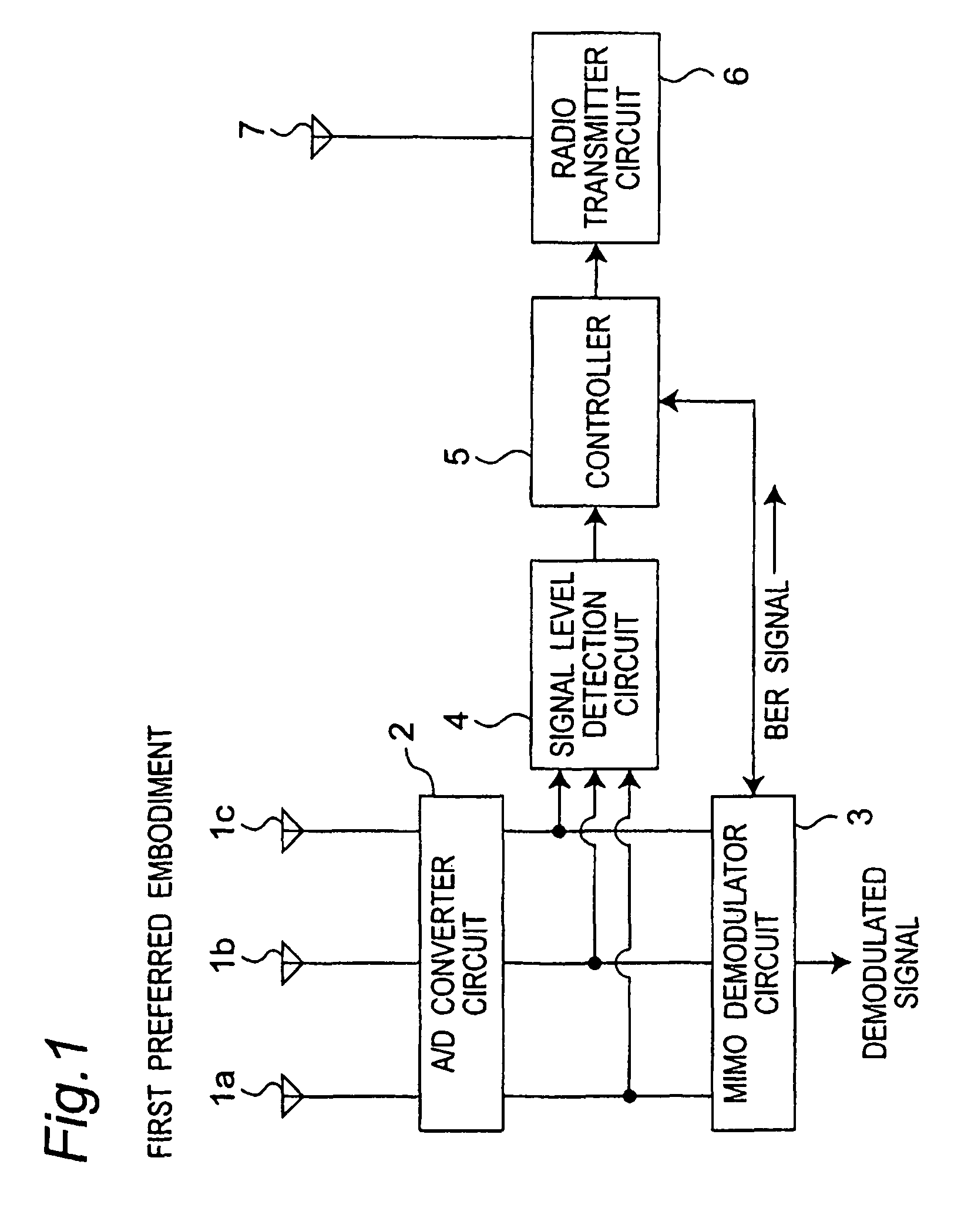
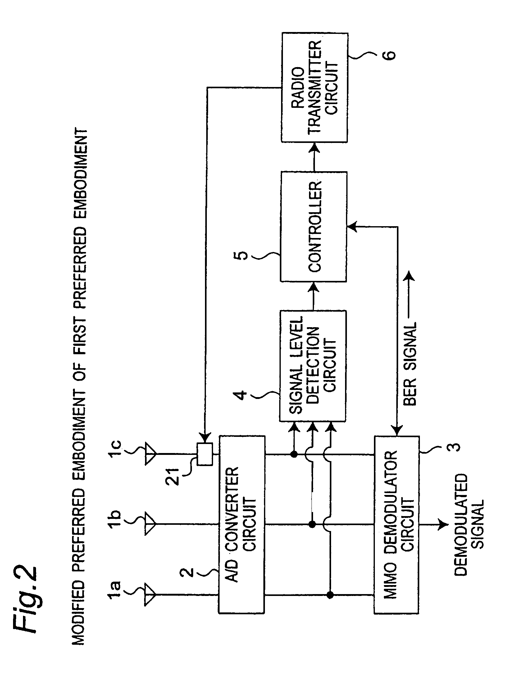
[0039]FIG. 1 is a block diagram showing a configuration of a MIMO antenna apparatus according to a first preferred embodiment of the present invention. Referring to FIG. 1, the MIMO antenna apparatus according to the present preferred embodiment will be described below. Referring to FIG. 1, three different radio signals transmitted from a sender-side radio station apparatus (not shown) using a certain MIMO communication method are received through three receiving antenna elements 1a, 1b, 1c, respectively, and the respective received radio signals are inputted into an analog / digital (A / D) converter circuit 2. The A / D converter circuit 2 includes three A / D converters each corresponding to each one of the input radio signals, performs an A / D conversion process on each one of the radio signals by these A / D converters individually, and outputs the processed signals (hereinafter, referred to as “received signals”) to both of a MIMO demodulator circuit 3 and a signal level detection circui...

second preferred embodiment

[0092]FIG. 11 is a block diagram showing a configuration of a MIMO antenna apparatus according to a second preferred embodiment of the present invention. The MIMO antenna apparatus according to the present preferred embodiment is characterized by having, in addition to the constituent elements of the MIMO antenna apparatus shown in FIG. 1, an adaptive demodulator circuit 12, and a switch circuit 11 for connecting an A / D converter circuit 2 to either a MIMO demodulator circuit 3 or the adaptive demodulator circuit 12. The MIMO antenna apparatus according to the present preferred embodiment is also characterized in that if any interference wave signal is received, the switch circuit 11 is moved under predetermined conditions so that the adaptive demodulator circuit 12 performs a demodulation process using recurrent and repetitive calculations.

[0093]The switch circuit 11 includes three switches corresponding to three received signals outputted from the A / D converter 2, respectively. Th...


PUM


Abstract

A MIMO antenna apparatus receives a plurality of radio signals modulated and transmitted by a sender-side radio station apparatus using a MIMO (Multi-Input Multi-Output) communication method with a number of data streams and a modulation and demodulation method. The MIMO antenna apparatus includes a plurality of antenna elements, detection means, MIMO demodulation means, radio transmission means, and control means. The control means controls the sender-side radio station apparatus by making the radio transmission means transmit the control signal, and controlling the MIMO demodulation means, so as to change, based on the received signal levels and the signal quality, at least one of the number of data streams and the modulation and demodulation method for the MIMO communication method used by the sender-side radio station apparatus and the MIMO demodulation means.

Description

BACKGROUND OF THE INVENTION[0001]1. Field of the Invention[0002]The present invention relates to an antenna apparatus for use in a radio communication apparatus which is controlled so as to achieve high-speed communication with increased communication capacity as well as keep high communication quality in mobile communication through a mobile telephone or the like. The present invention particularly relates to a MIMO antenna apparatus controlling the number of streams and the modulation and demodulation method, and a radio communication apparatus provided with the MIMO antenna apparatus.[0003]2. Description of the Related Art[0004]There has been known an antenna apparatus using MIMO (Multi-Input Multi-Output) technique for simultaneously transmitting and / or receiving radio signals on a plurality of channels using a plurality of antenna elements, and such antenna apparatus includes, for example, a MIMO antenna apparatus disclosed in the Japanese patent laid-open publication No. 2004-...

Claims


Application Information

Patent Timeline
Patent Type & Authority Patents(United States)
IPC IPC(8): H04W4/00
CPCH04B7/0413H04L1/0002H04B17/382H04L1/0625H04B17/309H04L1/0015
Inventor YAMAMOTO, ATSUSHIIWAI, HIROSHIKATO, AKIRAAMARI, SATORU
Owner INVT SPE LLC
Learn More