
System and method for multi-directional positioning of projected images

a projection image and multi-directional technology, applied in the field of image projection, can solve the problems of inability to provide an active viewing experience to the viewer, and achieve the effect of reducing the number of projections

Inactive Publication Date: 2010-09-14
SONY CORP +1
View PDF20 Cites 1 Cited by
  • Summary
  • Abstract
  • Description
  • Claims
  • Application Information

AI Technical Summary

Benefits of technology

The patent describes a projection system and method that can display images on irregular surfaces and adjust to the characteristics of the environment. The system includes an image projection element and motion control elements that can change the direction and angle of the image output. The image can be modified based on the characteristics of the environment and the motion control elements. The system can be used in various applications such as entertainment, information technology, and communications. The projection system can be used in different locations and can be adapted to different needs. The technical effects of the patent include the ability to display images anywhere and the flexibility to adjust to different environments and user needs.

Problems solved by technology

However, in developing the system and method taught herein, it has been recognized that conventional projectors are unable to provide an active viewing experience that surrounds the viewer.

Method used


Image

  • System and method for multi-directional positioning of projected images
  • System and method for multi-directional positioning of projected images
  • System and method for multi-directional positioning of projected images

Examples


Embodiment Construction

[0052]Referring more specifically FIG. 1 through FIG. 6, an embodiment of the invention will now be described in detail. It will be appreciated that the system may vary as to configuration and as to details of the parts, and that the method may vary as to the specific steps and sequence, without departing from the basic concepts as disclosed herein.

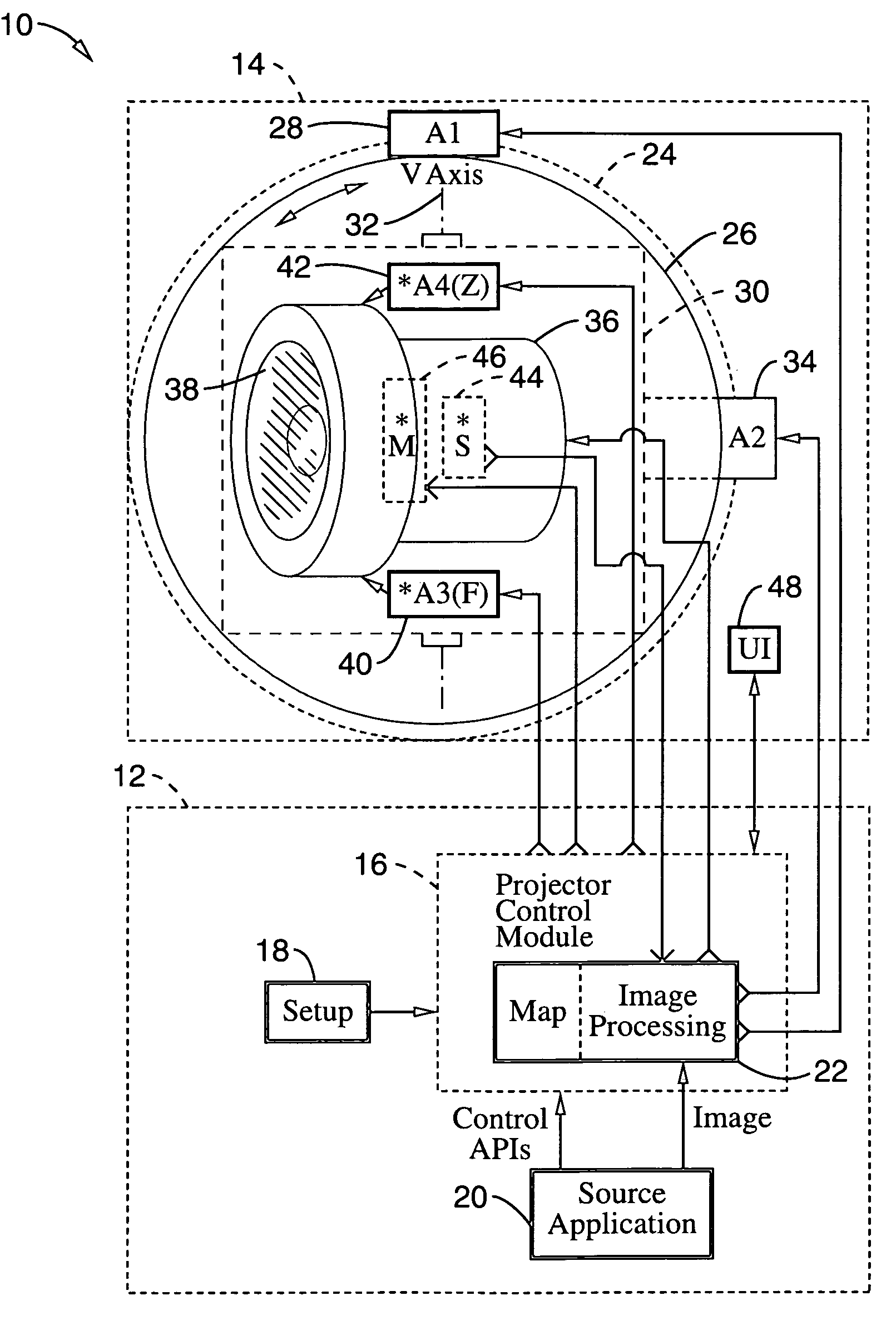
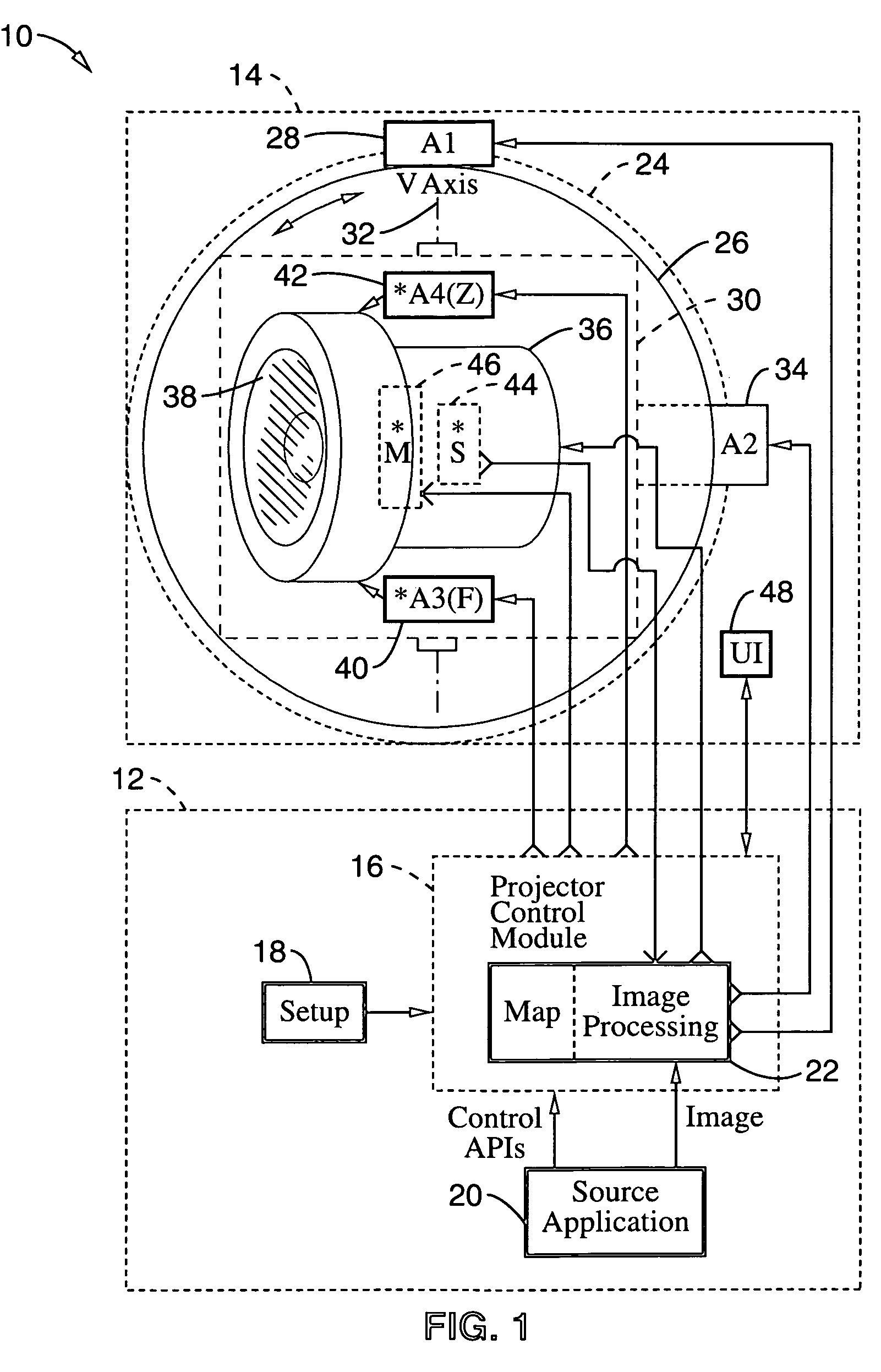
[0053]FIG. 1 illustrates an embodiment of a multi-directional output projection system 10 having a computer 12 coupled to a projection head 14. Although shown as a wired connection, it should be appreciated that computer 12 can alternatively communicate with projection head 14 over a network connection, wireless connection, or using power-line communication mechanisms.

[0054]Software for controlling the projection system is shown associated with computer 12, and includes a projector control module 16, setup module 18, source application 20, and map based image processing routine 22.

[0055]Projection head 14 is shown as including a stationar...


PUM


Abstract

A system and method of multi-directional projection in which the optical output from a projector is modified in response to characteristics of nearby surfaces, upon which projection can be directed. The multi-directional projection system can provide beneficial output as a primary indicator or a secondary indicating device that can be controlled by itself or synchronously with other devices, such as output from a computer monitor. One implementation incorporates an optical sensor coupled to the projector for registering object characteristics (e.g., distance, reflectance, texture, color, and ambient lighting), such as during a mapping operation performed across the pan and tilt range of the projector. The projection system preferably incorporates a focusing assembly and may include other controllable optical elements such as zoom. Control is preferably provided through commands within an application programming interface (API), such as executing on a personal computer or other form of computer device.

Description

CROSS-REFERENCE TO RELATED APPLICATIONS[0001]Not ApplicableSTATEMENT REGARDING FEDERALLY SPONSORED RESEARCH OR DEVELOPMENT[0002]Not ApplicableINCORPORATION-BY-REFERENCE OF MATERIAL SUBMITTED ON A COMPACT DISC[0003]Not ApplicableNOTICE OF MATERIAL SUBJECT TO COPYRIGHT PROTECTION[0004]A portion of the material in this patent document is subject to copyright protection under the copyright laws of the United States and of other countries. The owner of the copyright rights has no objection to the facsimile reproduction by anyone of the patent document or the patent disclosure, as it appears in the United States Patent and Trademark Office publicly available file or records, but otherwise reserves all copyright rights whatsoever. The copyright owner does not hereby waive any of its rights to have this patent document maintained in secrecy, including without limitation its rights pursuant to 37 C.F.R. §1.14.BACKGROUND OF INVENTION[0005]1. Field of Invention[0006]This invention pertains gen...

Claims


Application Information

Patent Timeline
Patent Type & Authority Patents(United States)
IPC IPC(8): G03B21/14G03B3/00G03B21/22G03B21/00
CPCG03B21/00G03B21/008
Inventor BIRMINGHAM, TOM
Owner SONY CORP
Learn More