Orthosis with multiple hinges

a technology of orthosis and hinges, applied in the field of orthosis or prosthesis, can solve the problems of orthosis having to be corrected afterward, difficult and laborious, and not readily predictable manipulation

Inactive Publication Date: 2010-09-14
KUNST & VAN LEERDAM IP
View PDF19 Cites 3 Cited by
  • Summary
  • Abstract
  • Description
  • Claims
  • Application Information

AI Technical Summary

Benefits of technology

[0010]Owing to the stated measures the loaded position can be reached by relative rotation of the orthosis parts without manipulation of the plaster model as discussed above, while the definitive position can be determined during use of the orthosis by adjusting the desired angle with the bounding means adapted for this purpose, whereby a result that is optimal for the user can be achieved in simple manner, without the later correction required in the known orthosis.
[0011]A second advantage of the measures according to the invention is that the rotation of the orthosis according to the invention corresponds better to the natural rotation of the joint in question, thereby removing a significant limitation in the movements of the relevant joint.
[0015]The orthoses known from the two cited publications have a hinge part on either side of the relevant joint. Such orthoses can be referred to as double-sided orthoses. According to the invention the device can advantageously have the feature that said structure is provided on only one side with hinge means. Better cosmetic results are possible with such a device, which is found to be greatly valued by users during tests. Furthermore, with a single-sided orthosis the construction of the multiple hinge according to the invention can be simpler than in the case of a double-sided orthosis.

Problems solved by technology

A first problem of known orthoses is that the construction of an orthosis generally takes place on the basis of a positive plaster model of the shape of the limb in a resting and non-loaded position.
The results of such a manipulation are however not readily predictable, which results in the orthosis having to be corrected afterward, which is difficult and labour-intensive.
For this reason the correction is not carried out in some cases, which results in a non-optimal orthosis for the user.
A second problem of known orthoses is that a rotation is generally only possible about one fixed main rotation axis of the orthosis which generally corresponds with the characteristic rotation axis of the joint for stabilizing.
This obstruction results in undesirable stresses on the joint and the limb parts.

Method used


Image

  • Orthosis with multiple hinges
  • Orthosis with multiple hinges
  • Orthosis with multiple hinges

Examples


Embodiment Construction

[0023]Corresponding components are designated in all the figures with the same reference numerals.

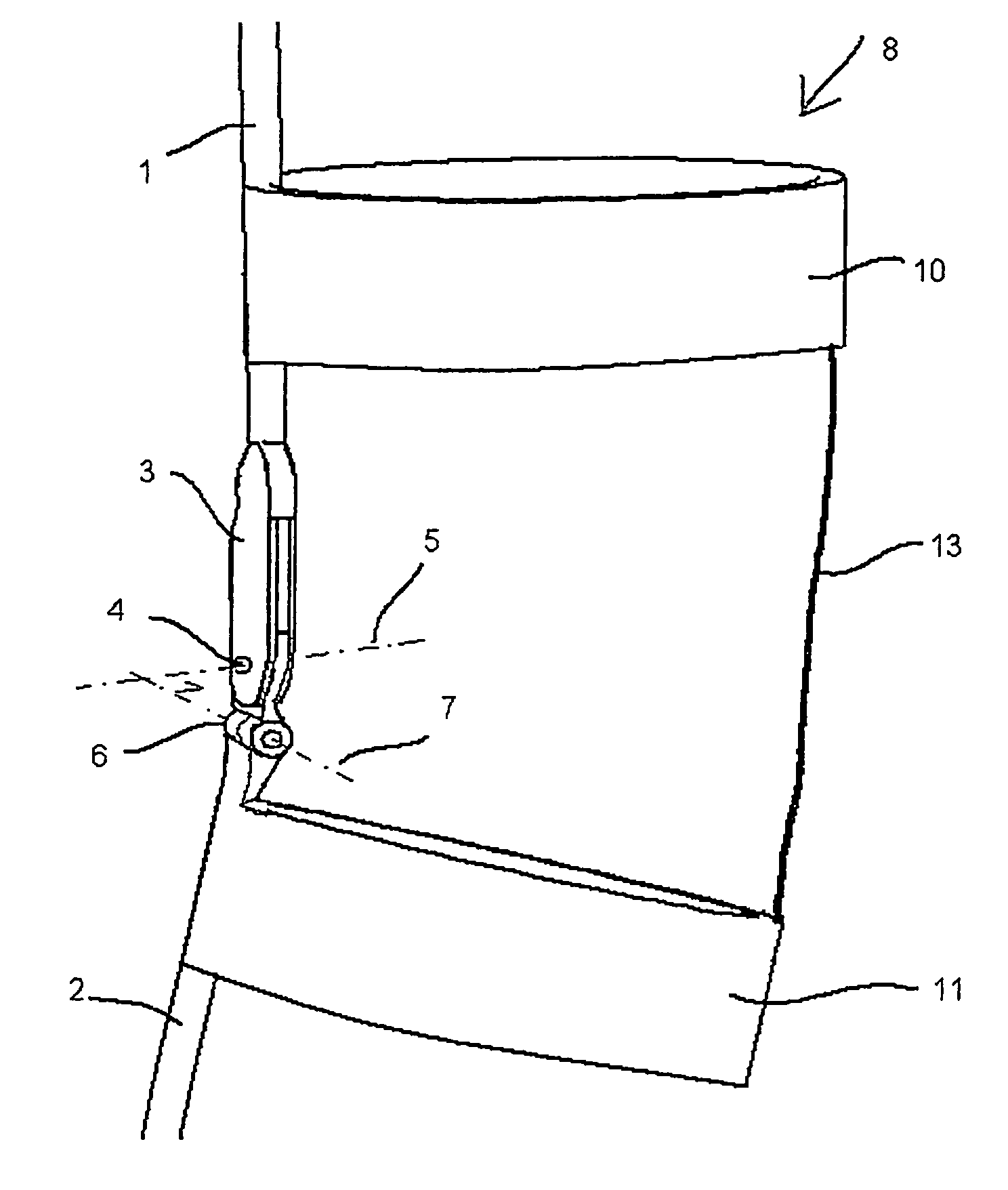
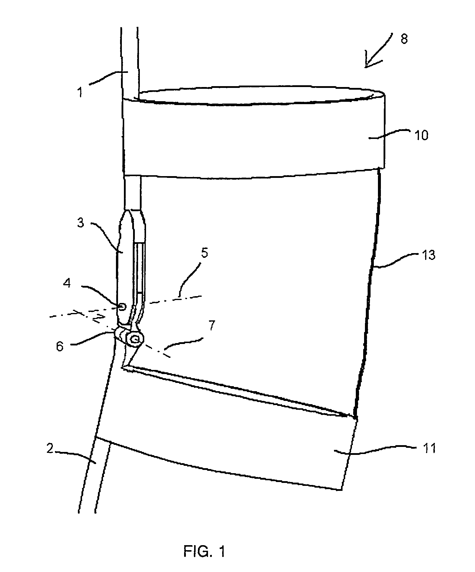
[0024]FIG. 1 show an orthosis comprising an upper rod 1 and a lower rod 2 which are coupled hingedly to each other by means of hinge means 3. Hinge means 3 comprise an upper hinge 4 with a pivot axis 5 and a lower hinge 6 with a pivot axis 7. The pivot axes 5 and 7 correspond respectively with the usual pivoting movement of the knee and a swivelling movement substantially perpendicular thereto.

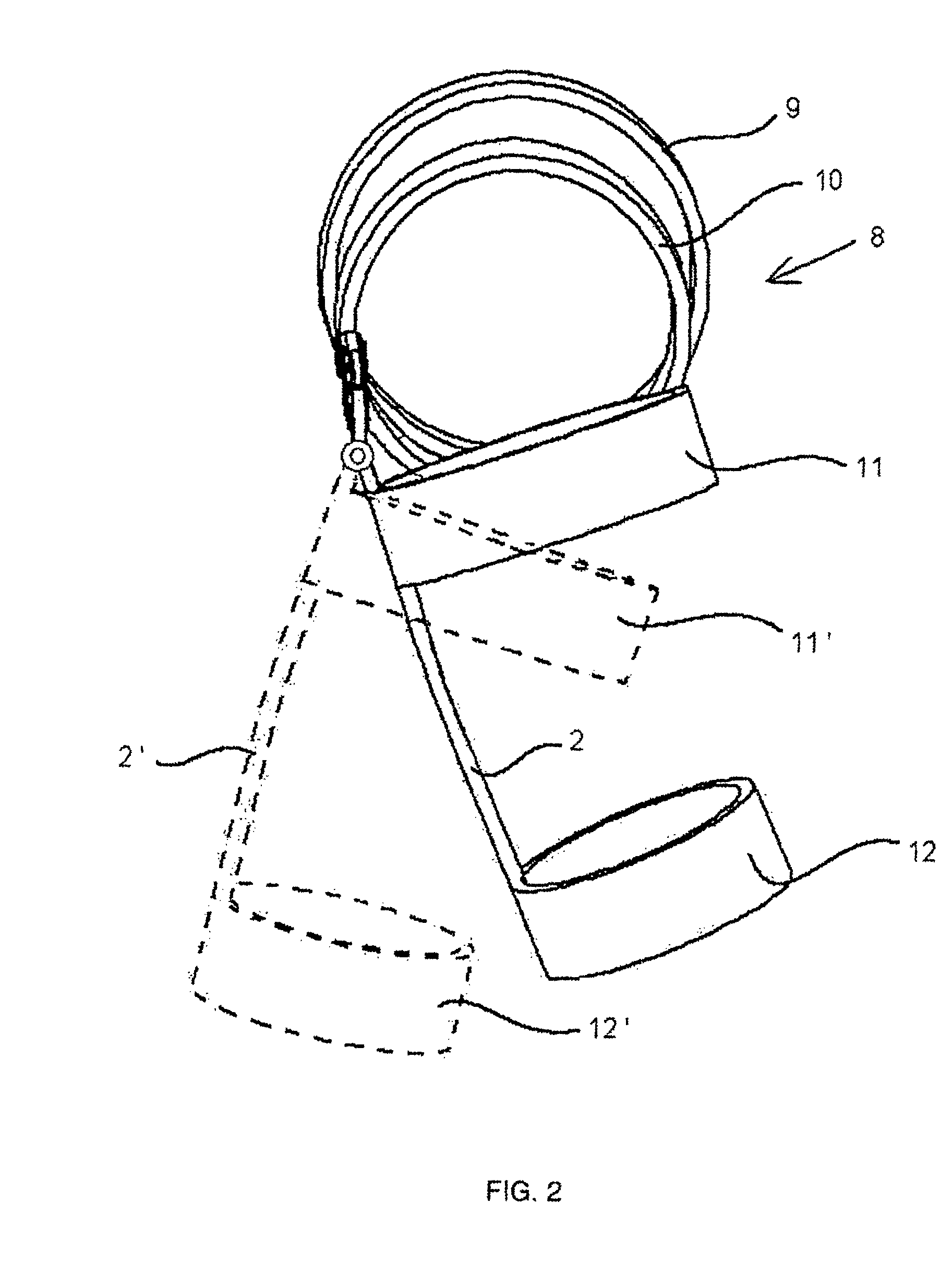
[0025]In order to fasten the orthosis 8 to the leg of a user, use is made of two sets of divisible rings with adjustable periphery, which in accordance with FIGS. 2, 3 and 4 are designated respectively 9, 10, 11, 12.

[0026]The rings 10 and 11 are connected to each other by means of a flexible, tensively strong element 13, for instance a strap or cord of optionally adjustable length, such that this element 13 functions as limit to the swivelling movement of hinge 6 and allows the knee to move unhind...


PUM


Abstract

An orthopedic device has a structure with two substantially rigid parts, for instance, rods, which rods are coupled to each other by a hinge apparatus and each rod attaches to a fastener for optional temporary fastening to a limb part, wherein a pivot axis of the hinge apparatus extends in the region and in the direction of the pivot axis zone of the relevant joint. The device has an upper hinge and a lower hinge with pivot axes. The respective pivot axes of which extend in directions which make an angle with each other of 90°±40°.

Description

BACKGROUND OF THE INVENTION[0001]The invention relates to an orthopaedic device, in particular a prosthesis or an orthosis, for the purpose of replacing respectively supporting the function of at least one part of a human limb with a pivotable joint, for example a leg with a knee or an arm with an elbow, on either side of which joint there extend respective limb parts, such as a lower leg and an upper leg respectively a lower arm and an upper arm, which device comprises:[0002]a structure comprising two substantially rigid parts, for instance a rod, which parts are coupled to each other by means of hinge means and each comprise fastening means for optional temporary fastening to a limb part,[0003]wherein a pivot axis of the hinge means extends at least more or less in the region and in the direction of the pivot axis zone of the relevant joint.[0004]Such a device is known from for instance U.S. Pat. No. 5,792,086 and GB-A 2 099 309.SUMMARY OF THE INVENTION[0005]An orthosis is an assi...

Claims


Application Information

Patent Timeline
Patent Type & Authority Patents(United States)
IPC IPC(8): E05D3/10A61B19/00A61F5/37A61F5/00A61F5/01
CPCA61F5/0125Y10T16/5472A61F2005/0167A61F2005/0134
Inventor BESSELINK, MARK STEFANVAN LEERDAM, NICOLAAS GERARDUS ADRIANUSVAN DER WOUDE, JURRIE
Owner KUNST & VAN LEERDAM IP
Why Eureka
Try Eureka