
Torque-limiting device in a mechanism used to transform a rotational movement into a reciprocating linear movement or vice versa

a technology of torque limitation and rotating force, which is applied in the direction of picking devices, agriculture tools and machines, applications, etc., can solve the problems of reducing the sealing effect, reducing the rotational capacity of the rod, and affecting the sealing effect, so as to reduce the force necessary, reduce the friction, and reduce the radius of limitation

Inactive Publication Date: 2006-02-09
HISPAES
View PDF4 Cites 3 Cited by
  • Summary
  • Abstract
  • Description
  • Claims
  • Application Information

AI Technical Summary

Benefits of technology

"This patent describes a device that limits the torque in a mechanism used to transform rotational movement into linear movement. The device includes a traveling end stop that moves along flat tracks in the mechanism, preventing torsional deformation and reducing the force required to counteract the applied torsion stresses. The device also reduces friction between the rear end stop and its associated guide. The technical effects of this device include a relatively large radius of limitation, a reduction in the force necessary to counteract the applied torsion stresses, and a reduction in friction between the rear end stop and its associated guide."

Problems solved by technology

This possibility of free rotation prevents any torsion moment produced on the said gripping member, for example, caused by operation with the tree's branches (returning in any direction), being transmitted to the rod via the mobile element, which could have harmful effects on the rod itself, the rod's crankpin, the mobile element, the articulated joint between the rod base and the mobile element etc.
However, in certain applications, it may be convenient for the rotational capacity of the rod to be limited at the same time as limiting the transmission of torsion stresses; for example, in a lightweight, portable mechanical harvester, such as the one described in document ES-A-1049600, belonging to the same applicant.
Although this arrangement prevents the free rotation of the mobile element on its own torsion axis, without preventing its rocking vibratory movement, sealing becomes very difficult to achieve when the guide of this rocking movement communicates with the vibration-producing mechanism's oil sump.
However, the sump is not perfectly leak-tight and the guidance of the mobile element is deficient.

Method used


Image

  • Torque-limiting device in a mechanism used to transform a rotational movement into a reciprocating linear movement or vice versa
  • Torque-limiting device in a mechanism used to transform a rotational movement into a reciprocating linear movement or vice versa
  • Torque-limiting device in a mechanism used to transform a rotational movement into a reciprocating linear movement or vice versa

Examples


Embodiment Construction

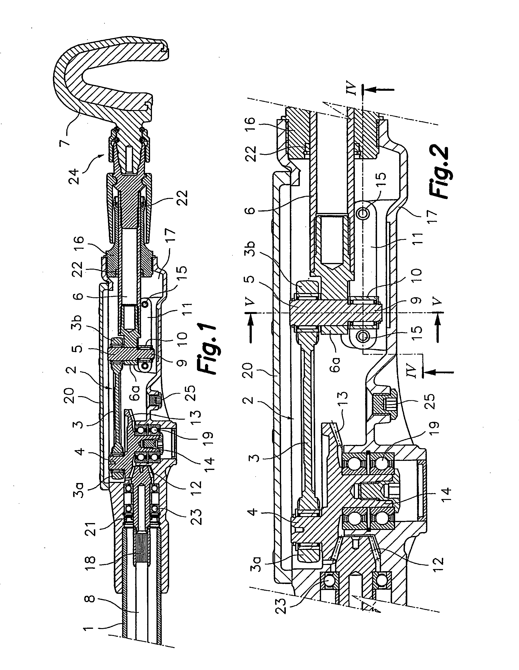
[0019] First referring to FIG. 1, which is a partial representation of a lightweight portable mechanical harvester similar to the one described in the cited document ES-A-1049600, of the same applicant. It must be pointed out, however, that although the device of this invention is very suitable for this type of apparatus, its application is not limited to the same and its description is only provided as an example.

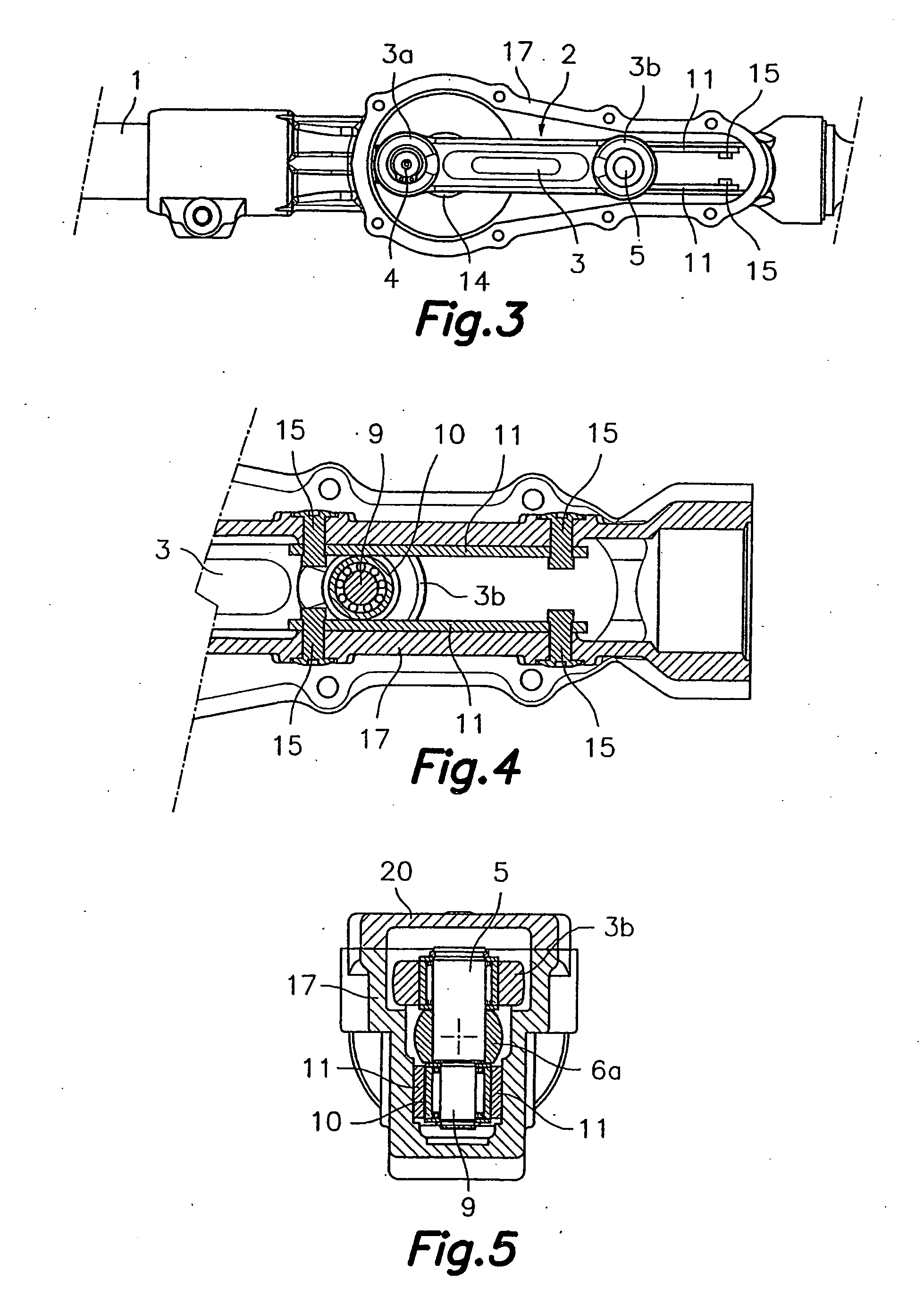
[0020] The apparatus of FIG. 1 is of the type comprising a tubular support 1 containing a rotational movement power shaft 8 coupled by a first end to a rotational power takeoff point or engine (not shown) and by a second end to a vibration producing mechanism 2 that includes a connecting rod 3 that is connected by its head 3a to an eccentric crankpin 4 of a rotating crank and by its base 3b to the end of a mobile element 6 via a hinge pin 5, and which is linearly guided by a guide 16 fixed to a casing 17 of the said vibration-producing mechanism. The distal end of the cit...


PUM


Abstract

The mechanism is of the type that comprises a connecting rod connected by its head to a crankpin of a rotating crank, and by its base to a linearly guided mobile element. The device comprises a travelling end stop joined to an articulation close to one end of the mobile element. The travelling end stop moves with a rocking movement between two flat tracks that face each other and which are parallel to the direction of movement of the travelling end stop. In the presence of torsional stresses applied to the mobile element, the travelling end stop move in contact with one or the other of the said tracks preventing or limiting torsion deformation of the connecting rod and / or the mobile element and the presence of strains in the mechanism.

Description

FIELD OF THE INVENTION [0001] This invention concerns a torque-limiting device in a mechanism used to transform a rotational movement into a reciprocating linear movement or vice versa. [0002] The device of this invention is applicable to any machine that includes a mechanism used to transform a rotational movement into a reciprocating linear movement or vice versa in which the reciprocating linear movement element may be subject to torsion stresses in spite of being linearly guided, such as for example, a reciprocating saw. More specifically, the device of this invention is applicable in a portable mechanical harvester, in which the reciprocating linear movement element has a gripping device at its distal end that is used to grip a branch or secondary trunk of a tree or bush. TECHNICAL BACKGROUND [0003] As an example of a portable mechanical harvester, the one described in patent WO 98 / 00190 of the same applicant may be cited, that comprises a motor which, by means of a centrifugal...

Claims


Application Information

Patent Timeline
Patent Type & Authority Applications(United States)
IPC IPC(8): A01D46/00A01D46/26A01D75/18
CPCA01D46/26A01D2046/266A01D75/18
Inventor GURRI MOLINS, JOSE
Owner HISPAES
Learn More