Myocardial injector

a technology of myocardial veins and injectors, which is applied in the field of myocardial vein injectors, can solve the problems of catheters themselves contacting the organ wall, catheters contacting the distal end of the needle, and causing the catheter to contact the organ wall, etc., and achieves the effect of preventing unwanted catheter advancement and without risk of damaging the myocardial tissu

Active Publication Date: 2010-09-28
SCHATZ RICHARD A
View PDF10 Cites 71 Cited by
  • Summary
  • Abstract
  • Description
  • Claims
  • Application Information

AI Technical Summary

Benefits of technology

[0008]In order to perform an intra myocardial injection, the injector is placed at a desired position near or adjacent myocardial tissue. During this placement, the abutment member is in its first configuration. Thereafter, the rod is used to move the abutment member in the distal direction through the distal end of the catheter until the abutment member reaches its second configuration. In its second configuration, the distal portion of the abutment member flares radially and the abutment member is substantially fan shaped. Because the abutment member extends distally from the catheter, the abutment member provides a barrier between the catheter and the myocardial tissue. Therefore, when the needle is advanced and the needle tip penetrates the myocardial tissue to perform the injection, the abutment member prevents contact between the catheter and the myocardial tissue, preventing unwanted advancement of the catheter. As a result, the surgeon may confidently advance the needle without risk of damaging the myocardial tissue with the catheter.

Problems solved by technology

In these applications, if the needle of the injection catheter inadvertently passes through the wall, the therapeutic or diagnostic agents that are dispensed from the distal end of the needle will not be effectively delivered to the target tissue.
Further, because the injection procedure often requires the thrust of a needle in the distal direction, the required motion can cause the catheter itself to contact and perforate or otherwise injure the wall of the organ.

Method used


Image

  • Myocardial injector
  • Myocardial injector
  • Myocardial injector

Examples


Embodiment Construction

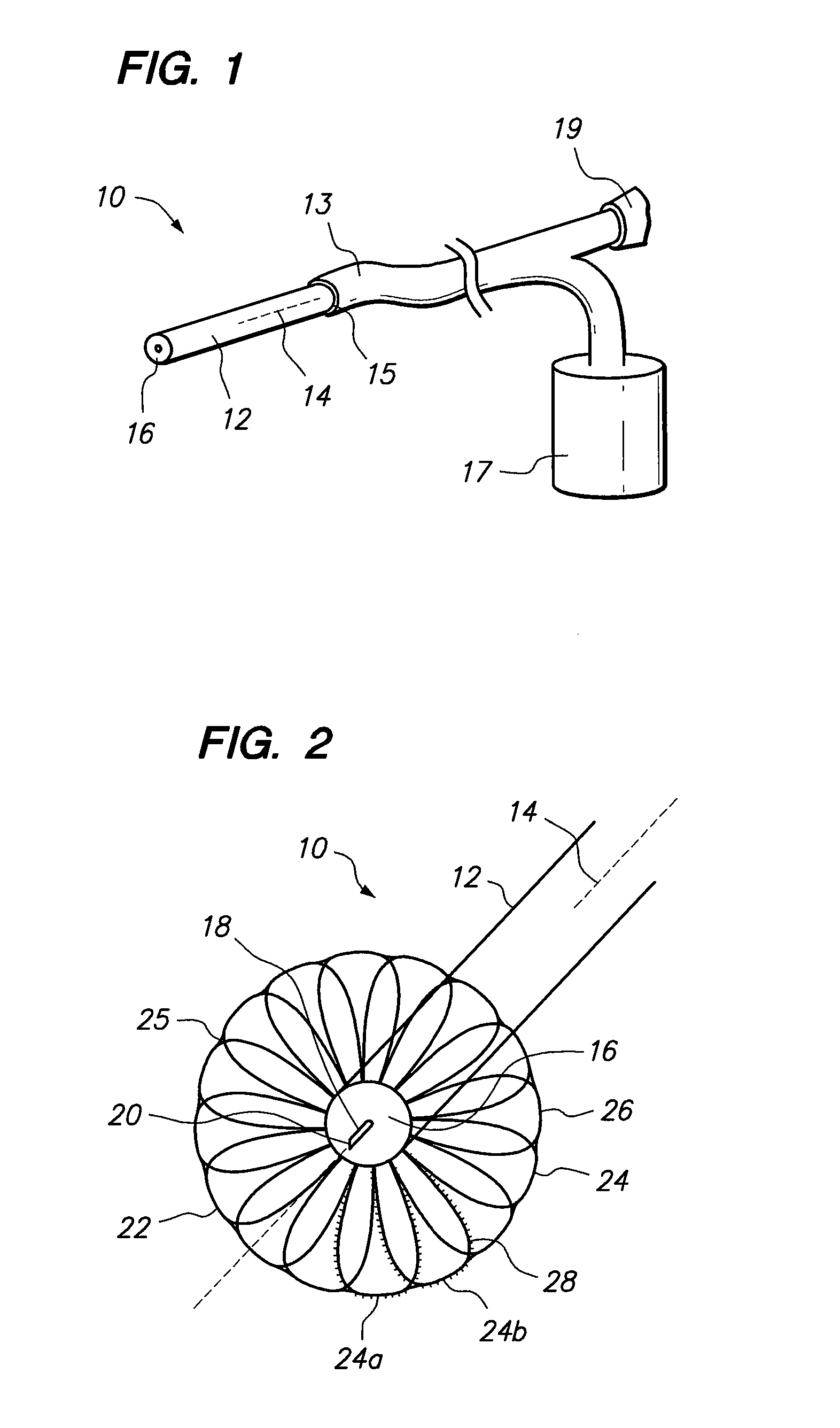
[0015]Referring initially to FIG. 1, an intra myocardial injector in accordance with the present invention is shown, and is generally designated 10. As shown in FIG. 1, the injector 10 includes a catheter 12 that extends along an axis 14 from a proximal end 15 to a distal end 16. As is shown, the proximal end 15 of the catheter 12 is connected to tubing 13. For purposes of the present invention, the tubing 13 is in fluid communication with a vessel 17 for holding medicament or other fluid for medical treatment. As is further shown, the tubing 13 also includes a port 19 that provides access for manipulation of internal components of the catheter 12.

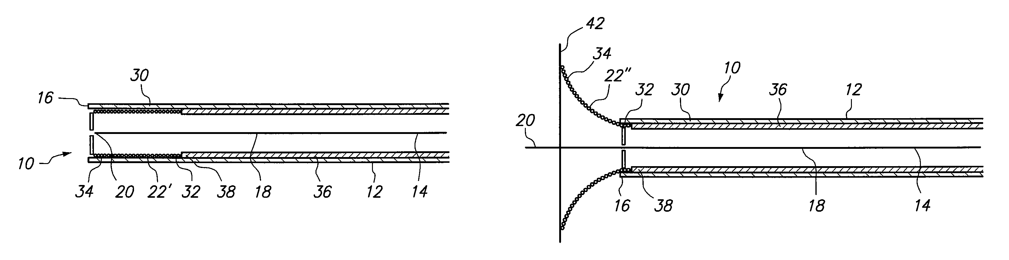
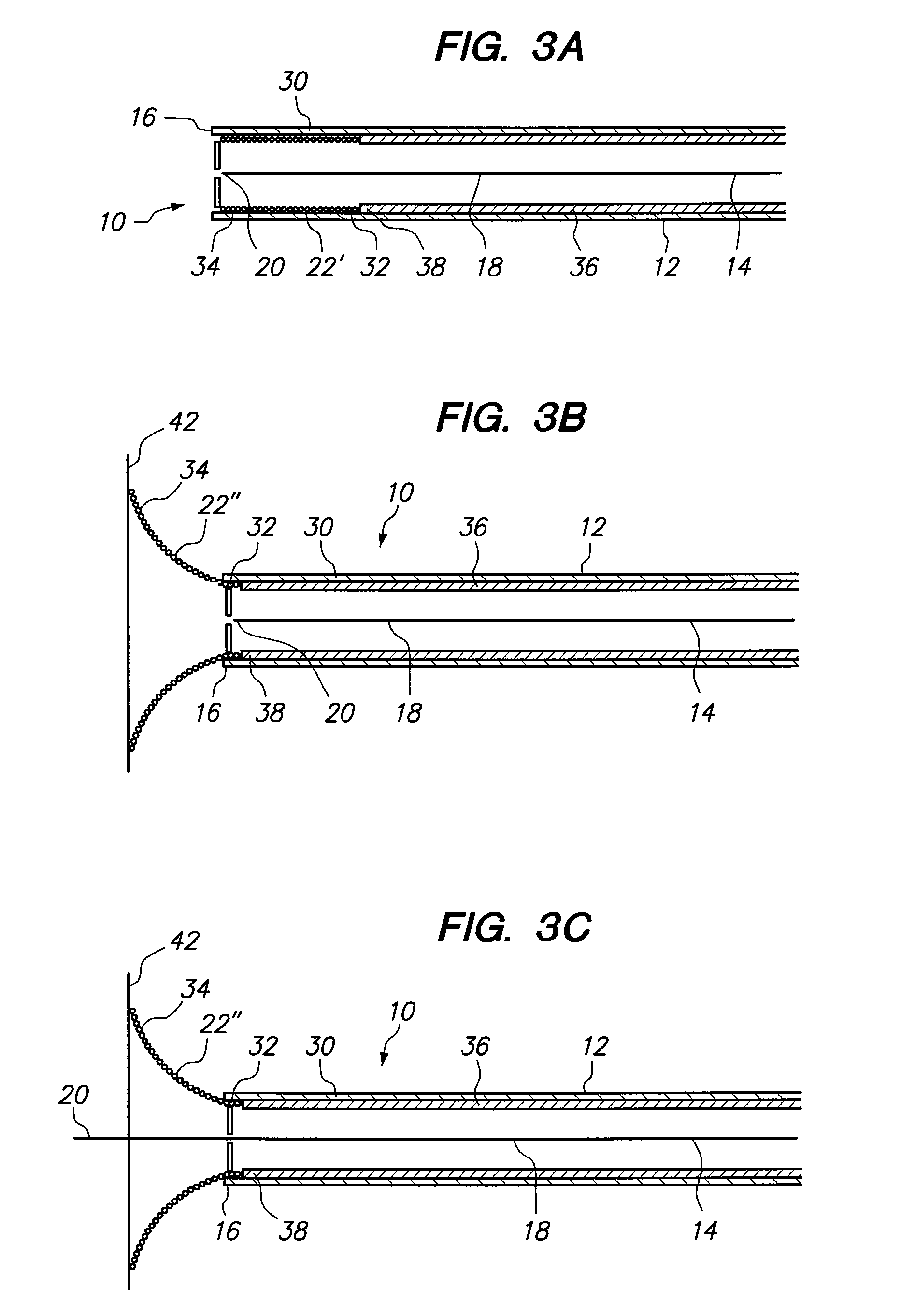
[0016]Referring now to FIG. 2, the injector 10 is shown to include a needle 18 that terminates at a needle tip 20. As shown in FIG. 2, the needle 18 has been advanced so that the needle tip 20 extends beyond the distal end 16 of the catheter 12. Further, the injector 10 is shown to include an abutment member 22. As shown, the abutment memb...


PUM


Abstract

A device is provided for performing intra myocardial injections. The device comprises a needle, a catheter formed with a lumen, and an abutment member mounted within the lumen for axial movement. The abutment member is movable between a first configuration, wherein it is substantially tube-like and is positioned within the lumen of the catheter, and a second configuration, wherein it extends beyond the distal end of the catheter and is substantially radially flared. Before the needle is advanced to perform an injection, the abutment member is moved to its second configuration to prevent contact between the catheter and the myocardial tissue during the injection.

Description

FIELD OF THE INVENTION[0001]The present invention pertains generally to devices and methods for delivering medicaments to a patient. More specifically, the present invention pertains to devices and methods for performing intra myocardial injections. The present invention is particularly, but not exclusively, useful as a device and method for advancing a needle from a catheter to perform an intra myocardial injection while protecting the myocardial tissue from contact with the catheter.BACKGROUND OF THE INVENTION[0002]Intravascular catheters are used in a wide variety of medical procedures by inserting the catheter into the vascular system of the patient at an easily accessible location. Thereafter, the tip of the catheter is advanced through the vasculature to a desired target site. In this manner, virtually any target site in the patient's vascular system may be remotely accessed. Of particular interest here are those medical procedures that require the use of injection catheters t...

Claims


Application Information

Patent Timeline
Patent Type & Authority Patents(United States)
IPC IPC(8): A61M5/178
CPCA61M25/0084A61M29/02A61B2017/00243A61M2025/0096A61M2025/0656
Inventor SCHATZ, RICHARD A.
Owner SCHATZ RICHARD A
Why Eureka
Try Eureka