Counter-balance weight for a modular safety rail

a safety rail and counterbalance weight technology, applied in the direction of manufacturing tools, roads, traffic signals, etc., can solve the problems of not being as aesthetically pleasing and costly to manufactur

Inactive Publication Date: 2005-09-13
KEE KLAMP LTD
View PDF22 Cites 13 Cited by
  • Summary
  • Abstract
  • Description
  • Claims
  • Application Information

AI Technical Summary

Benefits of technology

[0009]The present invention seeks to provide means whereby at least some of the aforedescribed disadvantages of the conventional counter-balance weight may be mitigated or overcome.
[0021]It is further preferred that the distance by which the edge regions lie spaced inwards from the respective lines of intersection of the shorter and longer sides of the isosceles triangle are each at least half of the maximum dimension of the outer surface of the boss region as considered in a direction parallel with the longer side of the triangular shape. Accordingly, when two of the counter-balance weights are laid side by side, with respective edge regions slightly spaced apart, a third counter-balance weight may be positioned in an inverted orientation, with the inclined faces thereof supported by neighbouring inclined faces of each of said two spaced weights, and with the protruding boss formation lying between the spaced edges. The boss formation of the inverted weight is then positioned spaced from a support surface on which the two spaced weights are positioned. Thus a plurality of the spaced weights may readily be stacked in a compact manner with high weight to space ratio, and without risk of damage to a protruding boss formation.
[0030]The through-bore of each counter-balance weight may be of circular section whereby, in use, the counter-balance weight may readily be tilted about the longitudinal axis of the spacer member so as to rest uniformly on a support surface, such as a roof or ground surface, despite any localised inclination of the support surface.

Problems solved by technology

The aforedescribed construction as shown in FIG. 1 functions satisfactorily in use, but suffers the disadvantage of being costly to manufacture, by virtue for example of the need to weld the sleeve (12) to the plate (11), and is not as aesthetically pleasing as may be desirable for some installation locations.

Method used


Image

  • Counter-balance weight for a modular safety rail
  • Counter-balance weight for a modular safety rail
  • Counter-balance weight for a modular safety rail

Examples


Embodiment Construction

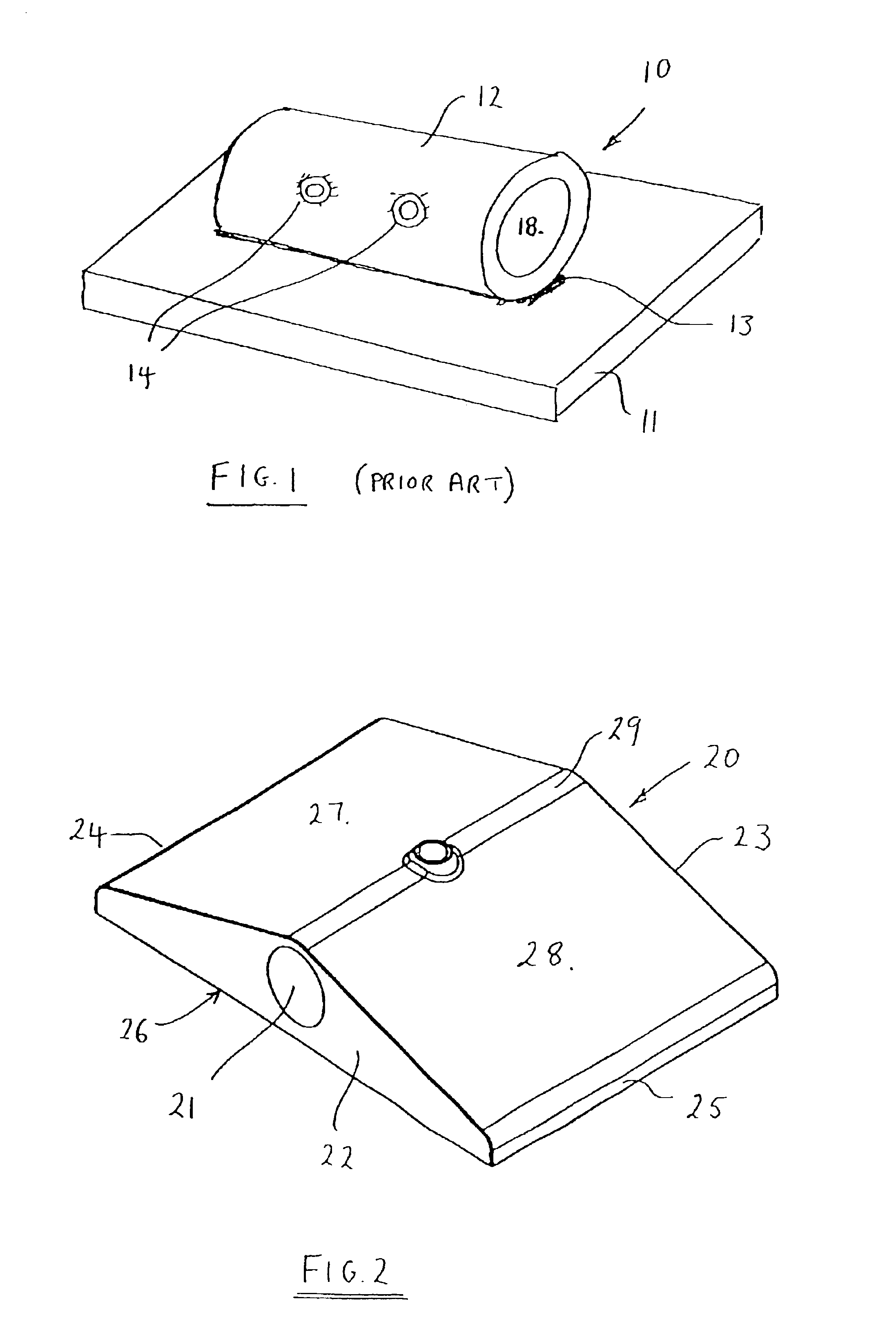
[0045]A counter-balance weight (20) comprises a substantially solid body member of grey cast iron.

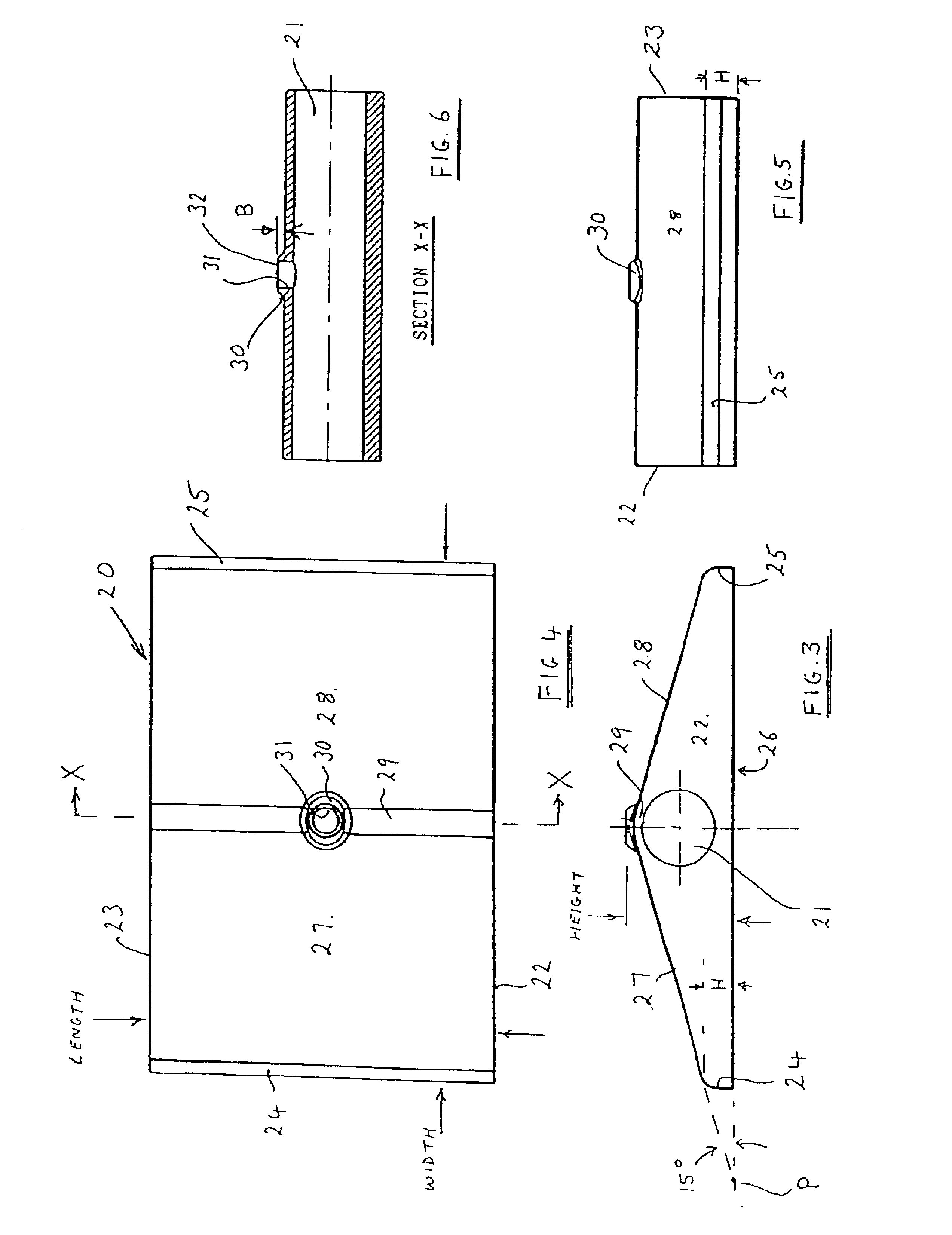
[0046]The weight is of a rectangular shape as viewed in plan, as shown in FIG. 4.

[0047]The body member is provided with a through-bore (21) which extends between transverse end faces (22, 23), each said end face being of a substantially triangular shape. The body member (20) is of a substantially symmetrical construction such that said triangular shape is that of an isosceles triangle, and the through-bore (21) is positioned mid-way between edge regions (24, 25).

[0048]The body member thus has a major face (26) which in use is intended to rest on a support surface such as that provided by a ground surface or roof surface, and a pair of shorter, relatively inclined upper surfaces (27, 28) which define therebetween an apex region (29). A boss (30) and screw threaded aperture (31) are provided mid-way along the length of the apex region, the boss protruding beyond said triangular shape. Ape...


PUM


Abstract

A counter-balance weight for a modular safety rail comprises substantially only a solid body of a compact shape wherein the volume of the material of the body is at least 20% of the volume of the smallest cuboid which is able to contain the body, the body defining a through-bore for receiving an end of a spacer member and the body further defining a screw-threaded aperture which extends through the body to communicate with said through-bore. The body may have a substantially triangular shape in transverse cross-section.

Description

BACKGROUND OF THE INVENTION[0001]This invention relates to a counter-balance weight for a modular type safety rail and in particular, though not exclusively, to a counter-balance weight and to a modular safety rail assembly suitable for use in providing free-standing roof edge protection.[0002]Modular type safety rail systems are well know and typically comprise straight lengths of metal tubing interconnected by connectors of different types such that, for example, two, three or four way interconnections of horizontally and vertically extending tubes may be achieved.[0003]Tubes serving as vertical posts of a safety rail, and to which horizontally extending tubes are connected, are supported by metal base plates of a rectangular shape and which, in use, rest on the surface of a roof. A flanged mounting socket typically is bolted to an upper surface of the plate, adjacent to one of the shorter edges of the rectangular shape, to provide location for the lower end of a vertical post.[00...

Claims


Application Information

Patent Timeline
Patent Type & Authority Patents(United States)
IPC IPC(8): E01F9/012E01F9/011E04G21/32
CPCE01F9/0124E04G21/3233Y10T16/82E01F9/692E04G21/3238
Inventor HIGGS, PHILIP MAURICEPRESANT, CHARLES WILLIAM STRATFORD
Owner KEE KLAMP LTD
Why Eureka
Try Eureka