Aircraft wing with wing tip device

a technology of wing tip and wing assembly, which is applied in the direction of airflow influencers, manufacturing tools, transportation and packaging, etc., can solve the problems of unsuitable arrangement, and achieve the effect of convenient installation and convenient installation

Inactive Publication Date: 2014-05-01
AIRBUS OPERATIONS LTD
View PDF7 Cites 13 Cited by
  • Summary
  • Abstract
  • Description
  • Claims
  • Application Information

AI Technical Summary

Benefits of technology

[0021]The step of installing the seal assembly preferably includes sliding the seal assembly along the gap with the bridging component at the interior side of the gap and the seal portion within the gap. Thus, the seal assembly can be easily installed into its final position in one process step.
[0022]The seal assembly preferably includes a reinforcing component fixed to the seal portion and arranged to extend across an exterior side of the

Problems solved by technology

At the wing-wing tip lower cover joint, however, such an arrangement is not suitable because the bead of sealant would

Method used


Image

  • Aircraft wing with wing tip device
  • Aircraft wing with wing tip device
  • Aircraft wing with wing tip device

Examples


Embodiment Construction

)

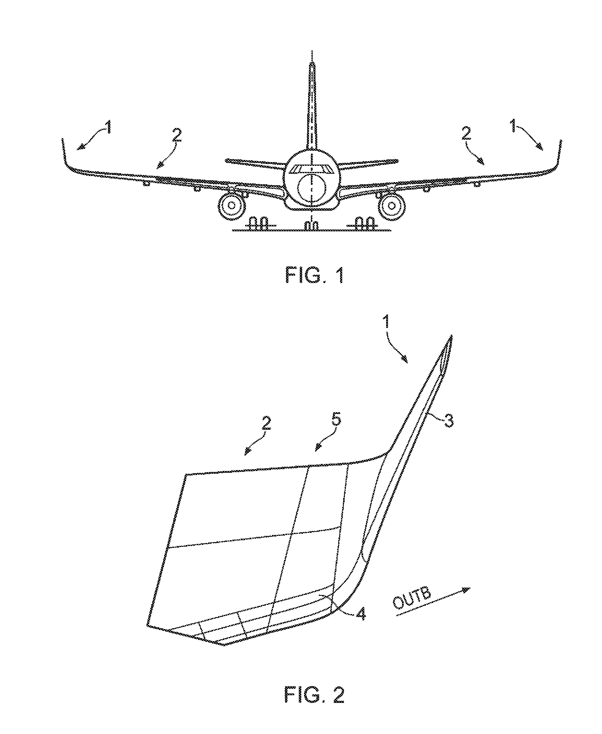
[0054]FIG. 1 illustrates a commercial jet aircraft including a wing assembly having a wing tip device 1 attached to the outboard end of a wing 2.

[0055]FIG. 2 illustrates the outboard end of the wing assembly in detail. The wing tip device 1 is substantially as described in WO2008 / 061739A, the contents of which are incorporated herein by reference. The wing tip device 1 generally comprises a substantially planar winglet 3 and a transition region 4 arranged between the wing 2 and the winglet 3. The transition region 4 has a curvature of local dihedral that increases from a low angle, or an angle of approximately zero, at or near the outboard end of the wing 2 and increases in the outboard direction. The winglet 3 extends upwardly from the transition region 4 and is inclined with respect to the vertical plane. In one example, the wing tip device 1 is approximately 2.5 metres tall and weighs approximately 120 kgs. The wing tip device 1 is used to reduce the induced drag on the wing lea...


PUM

PropertyMeasurementUnit
Lengthaaaaaaaaaa
Lengthaaaaaaaaaa
Lengthaaaaaaaaaa

Abstract

An aircraft wing assembly comprising a wing (2) having a wing box structure including an upper wing cover (7) and a lower wing cover (8), and a wing tip device (1) attached to the outboard end of the wing, the wing tip device including an upper cover (9) and a lower cover (10), wherein a gap (g) between opposing edges of the wing tip device lower cover (10) and the lower wing cover (8) is at least 5 mm, and further comprising a seal assembly (20) for aerodynamically sealing the gap (g), wherein the seal assembly (20) includes a bridging component (21) on an interior side of the gap (g), and a seal (22) which fills the gap (g) and is supported by the bridging component (21). Also, an aircraft having the wing assembly, and a method of attaching a wing tip device (1) to the outboard end of a wing (2).

Description

FIELD OF THE INVENTION[0001]The present invention relates to an aircraft wing assembly including a wing tip device attached to the outboard end of a wing, an aircraft having the wing assembly, and a method of attaching a wing tip device to the outboard end of a wing.BACKGROUND OF THE INVENTION[0002]An aircraft wing typically comprises a wing box structure including front and rear spars, a plurality of ribs extending between the spars, and an upper wing cover and a lower wing cover each extending between the spars. Various of the wing box components may be integrally formed.[0003]A wing tip device is a device that may be attached to the outboard end of a wing to reduce induced drag on the wing. In the case of e.g. an aircraft wing this can lead to improved fuel efficiency and reduced carbon emissions. Several different types of wing tip device are known, including the winglet, the wing tip fence, and the raked wing tip for example.[0004]The attachment between the outboard end of an a...

Claims


Application Information

Patent Timeline
IPC IPC(8): B64C3/00
CPCB64C3/00B64C23/069Y10T29/49826Y02T50/10B64C23/065
Inventor DAVIES, HUWMCKENNA, NIGEL
Owner AIRBUS OPERATIONS LTD
Why Eureka
Try Eureka