Cylinder head gasket

a gasket and cylinder head technology, applied in the direction of engine seals, rapid change measurement, instruments, etc., can solve the problems of insulating layer and therefore the line being damaged, the internal pressure of the cylinder being directly measured, and the cylinder being damaged. to achieve the effect of small defect toleran

Inactive Publication Date: 2006-02-28
ELRINGKLINGER AG +1
View PDF11 Cites 14 Cited by
  • Summary
  • Abstract
  • Description
  • Claims
  • Application Information

AI Technical Summary

Benefits of technology

[0008]It is therefore an object of the invention to provide a cylinder head gasket which can measure, with relatively small defect tolerances, the pressure in the cylinder of an internal combustion engine.
[0009]Another object of the invention is to provide a cylinder head gasket provided with means for measuring the pressure in the cylinder of an internal combustion engine which gasket is of simple design.
[0010]According to the invention, a metallic cylinder head gasket for an internal combustion engine is provided which is provided with one or more openings arranged next to one another corresponding to the combustion chambers of the internal combustion engine, and comprises at least one sheet-metal layer, a membrane which can be acted upon by the gas pressure of the combustion chamber being arranged adjacent to the edge of the at least one opening, the movement of which membrane can be picked up via a pressure sensor arranged in the sheet-metal layer. In this case, a bore which is closed on the combustion-space side by the membrane is provided between the outer edge of the sheet-metal layer and the edge of the opening of the particular combustion chamber, the membrane closing the bore on the combustion-chamber side, and the pressure sensor being able to be pressurized axially with respect to the bore by the membrane In a design of this type, the pressure can be measured directly without having to provide cavities which become dirty and therefore adversely effect the measurement. The design is simple at least in so tar as the feed lines to the pressure sensor can be accommodated in the bore without the risk of damage, and in that a simple axial construction is made possible in the bore, the construction permitting the pressure sensor to be accommodated in a relatively cool region of the cylinder head gasket.
[0011]This permits pressure measurements which have a standard deviation of approximately ±1 bar and are therefore equal to the pressure measurement using a conventional sheathed-element quartz pressure sensor. The effect of temperature on the pressure sensor can be kept very small and, if appropriate, can be readily corrected by means of an additive term.
[0012]This permits a very precise control of the combustion process in particular in diesel engines having common-rail or pump / nozzle injection. Deviations in the full-load injection quantity of individual cylinders, caused by tolerance-afflicted components in the injection elements, can be compensated for by the engine electronics on the basis of the measured values from the pressure sensors. The “safety margin” of the full-load peak pressure of the mechanical load limit of the engine structure can be significantly reduced. The pressure profile can be used to monitor the combustion on an individual cylinder basis Engine wear or malfunctions of the injection, exhaust-gas recirculation or boost pressure control can immediately be recognized on the basis of atypical peak pressures.

Problems solved by technology

However, this serves to monitor the gasket and not to monitor an internal pressure.
In this case, a direct measurement of the internal pressure of the cylinder is not possible or envisaged.
In this case too, a direct measurement of the internal pressure of the cylinder is not possible or envisaged.
Apart from the fact that the slot-like recess which is open towards the cylinder may become dirty or clogged up and therefore may result at least in falsifications of the measurement results, the pressure sensor is situated in a relatively hot region adjacent to the combustion chamber and, in addition, an insulating layer through which the lines from the pressure sensor are guided to the outside has to be arranged on the central gasket layer.
However, the insulating layer and therefore the lines may become damaged by beads of the outer gasket layers resting on them.
This requires not only a relatively large opening but also, for sealing reasons, the opening to be restricted by means of a relatively thick wall section, which has an adverse effect on the sensitivity of the measurement.

Method used


Image

  • Cylinder head gasket
  • Cylinder head gasket
  • Cylinder head gasket

Examples


Embodiment Construction

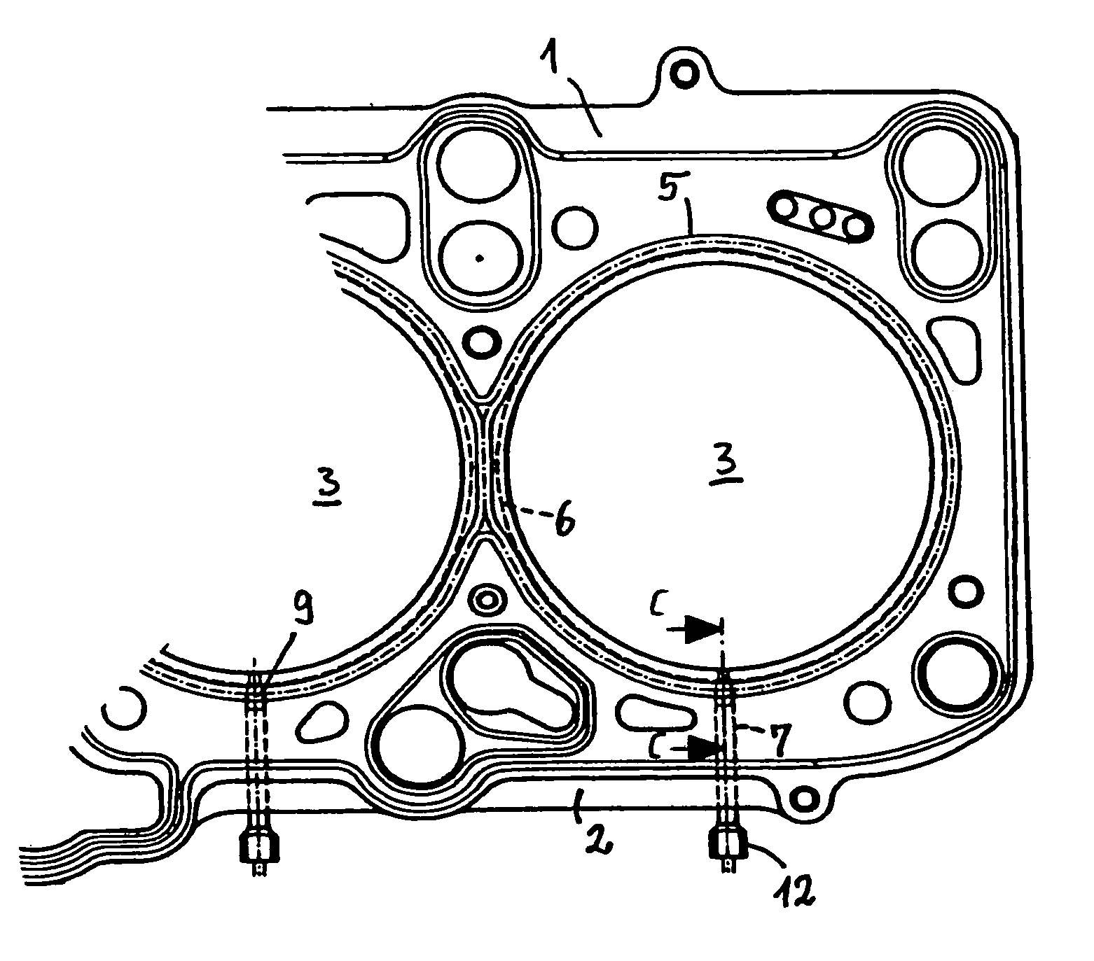
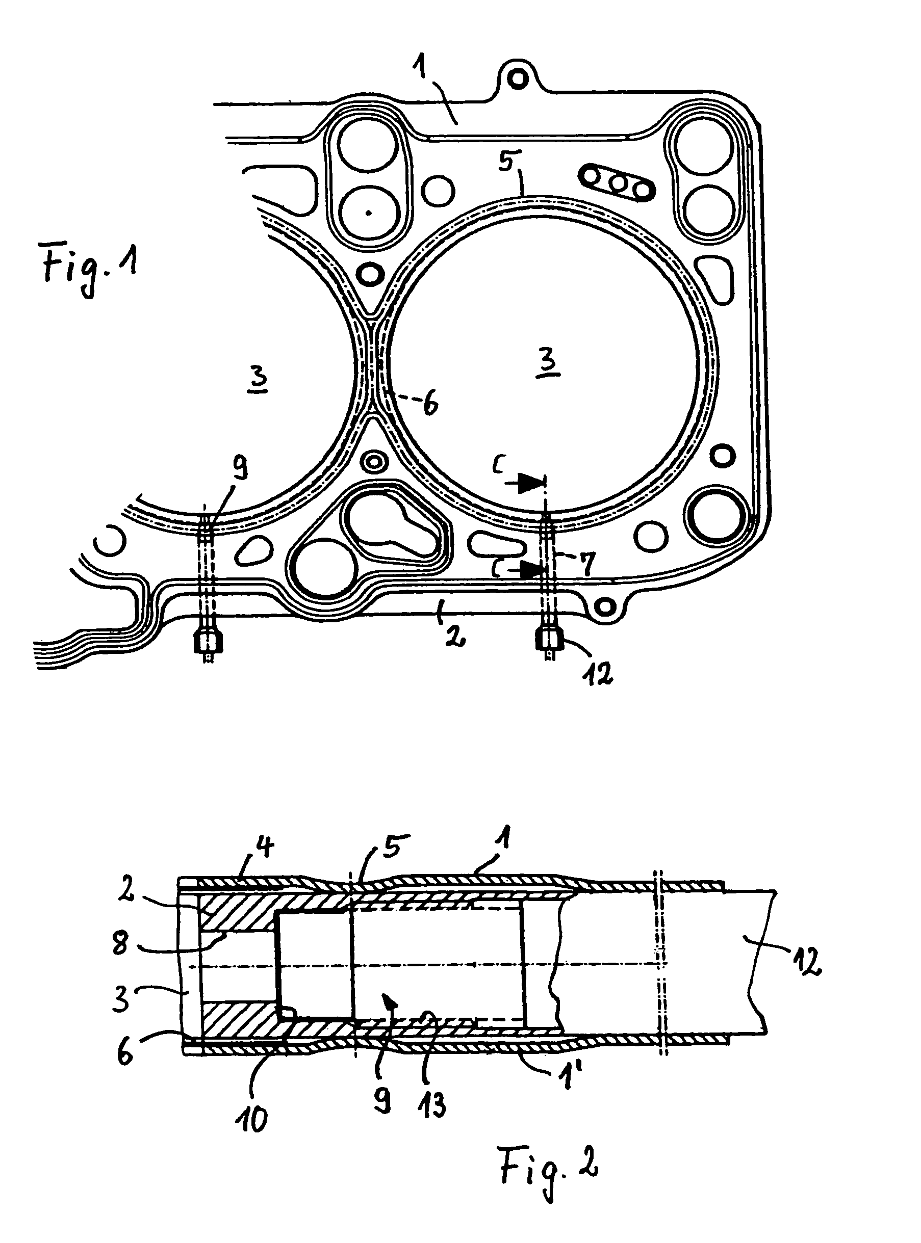
[0022]The metallic cylinder head gasket which is illustrated in FIG. 1 is three-layered, comprises two cover plates 1, 1′ and a carrier plate 2 and is provided with one or more openings 3 arranged next to one another corresponding to the combustion chambers of an internal combustion engine. The cover plates 1, 1′ are provided with a bead 5 around each opening 3 at a distance from the latter leaving a straight sheet-metal section 4 in the edge region of the opening, the beads 5 being orientated with their apexes towards each other and enclosing the carrier plate 2 between them.

[0023]An elevation 6 at the combustion chamber serving as a spring stroke limiter for the bead 5 is situated adjacent to the particular bead 5 on the straight sheet-metal section 4 around each opening 3, i.e. radially inwards from the particular bead 5, on the side on which the apex of the bead 5 is situated. The said combustion-chamber elevations are fastened to the cover plates 1, 1′, in particular are welded...


PUM

PropertyMeasurementUnit
pressureaaaaaaaaaa
pressureaaaaaaaaaa
gas pressureaaaaaaaaaa

Abstract

A metallic cylinder head gasket for an internal combustion engine having at least one combustion chamber. The gasket includes at least one sheet-metal layer having at least one opening corresponding to the at least one combustion chamber of the internal combustion engine and at least one bore extending from the outer edge to the edge of the opening. A membrane, closing the bore at the combustion-chamber side is exposed to the gas pressure of the combustion chamber. A pressure sensor disposed in the sheet-metal layer is pressurized axially relative to the bore by movement of the membrane by the gas pressure of the combustion chamber.

Description

FIELD OF THE INVENTION[0001]The invention relates to a cylinder head gasket as it is used in combustion engines to seal the gap between the cylinder block and the cylinder head.DESCRIPTION OF THE RELATED ART[0002]From GB 2,317,701 A it is known per se to provide a gasket between a container and its removable cover with a pressure sensor which is integrated in the gasket and measures the pressure exerted on the gasket, and, if the pressure drops below a threshold value, indicates that a leak has possibly occurred. However, this serves to monitor the gasket and not to monitor an internal pressure.[0003]DE 40 14 502 C2 discloses a compression-molded cylinder head gasket for an internal combustion engine, in which a sensor for sensing measured values from the region of the cylinder interior is placed into the gasket material before the compression takes place, after which the gasket is compressed in order to produce a gas-tight connection between the gasket material and embedded sensor....

Claims


Application Information

Patent Timeline
Patent Type & Authority Patents(United States)
IPC IPC(8): G01L23/22F02F11/00F02D35/00F16J15/08G01L23/06G01L23/10G01L23/16G01L23/18
CPCG01L23/10G01L23/16G01L23/222G01L23/22G01L23/18F02F11/00
Inventor DIEZ, ARMINEIFLER, GERALDCAVALLONI, CLAUDIOWOLFER, PETERSCHNEPF, MICHAEL
Owner ELRINGKLINGER AG
Why Eureka
Try Eureka