
Stator for an electric machine, and method for producing such a stator

a technology of electric machines and stators, which is applied in the direction of dynamo-electric machines, electrical apparatus, windings, etc., can solve problems such as contact problems with regard to control units, and achieve the effect of small toleran

Active Publication Date: 2017-12-21
ROBERT BOSCH GMBH
View PDF0 Cites 17 Cited by
  • Summary
  • Abstract
  • Description
  • Claims
  • Application Information

AI Technical Summary

Benefits of technology

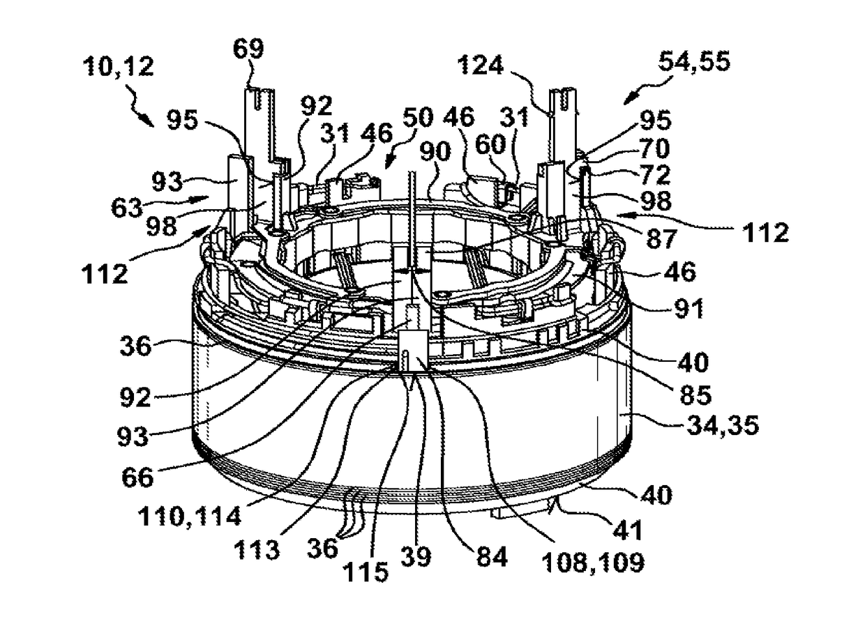
The invention provides an apparatus and method that eliminates manufacturing tolerances between parts, resulting in more exact positioning of terminal plugs with respect to a reference surface of the motor housing. This is achieved by integrating axial spacers onto the interconnect plate, allowing it to be directly supported on the stator body face surface without requiring additional structural elements.

Problems solved by technology

As a result, the plug connections to the control unit do not have a clearly defined axial position, which can give rise to contacting problems with regard to the control unit.

Method used


Image

  • Stator for an electric machine, and method for producing such a stator
  • Stator for an electric machine, and method for producing such a stator
  • Stator for an electric machine, and method for producing such a stator

Examples


Embodiment Construction

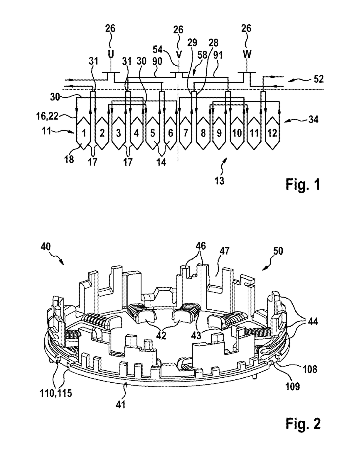
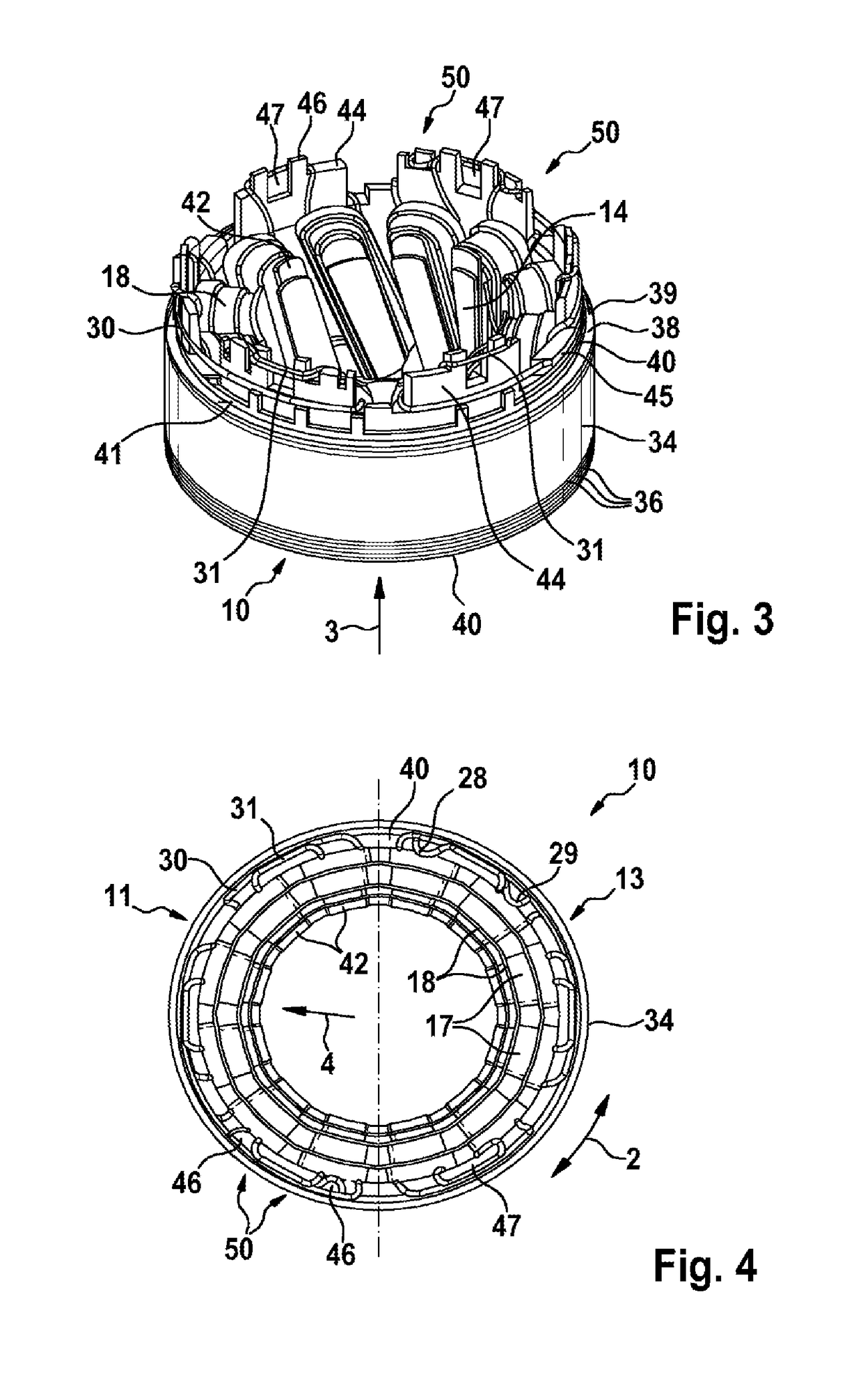
[0027]FIG. 1 schematically illustrates a cut-open stator 10, on the stator teeth 14 of which the winding diagram of an electrical winding 16 is illustrated. The stator 10 has for example twelve stator teeth 14, wherein in each case always exactly one sub-coil 18 is wound onto each stator tooth 14. Here, in each case two sub-coils 18 situated immediately adjacent to one another are connected by means of a short connecting wire 31 to form an adjacent sub-coil pair 17. The winding is commenced for example with a first wire start 28 on the second stator tooth 14, and a connecting wire 30 is led to the fifth stator tooth 14. Immediately after the fifth stator tooth 14, the sixth stator tooth 14 is wound, such that said sub-coil pair 17 is connected by means of the short connecting wire 31 of two immediately adjacent sub-coils 18. After the sixth stator tooth 14, the winding wire 22 is led by means of the connecting wire 30 to the third stator tooth 14, in order there to form a sub-coil p...


PUM


Abstract

The invention relates to a stator (10) and to a method for producing a stator (10) for an electric machine (12), comprising a stator body (34) which has radial stator teeth (14) for receiving sub-coils (17) of an electric winding (16). An insulating plate (40) with guide elements (44) for connection wires (30, 31) is arranged between the sub-coils (17) on an end face (39) of the stator body (34), and a separately produced wiring plate (52) is arranged axially over the insulating plate (40), said wiring plate having conductor elements (63) for electrically contacting the connection wires (30, 31) with customer-specific connection plugs (56) of a controller. The wiring plate (52) is supported directly on the end face (39) of the stator body (34) by means of spacers (84).

Description

BACKGROUND OF THE INVENTION[0001]The invention relates to the stator for an electric machine, and to an electric machine, and to a method for producing a stator.[0002]DE 10 2012 224 153 A1 has disclosed a stator of an electric machine, in the case of which an insulating lamination and an interconnect plate are arranged axially on a lamination stack. The stator is for example enwound with needle windings, wherein the individual sub-coils are connected to one another by means of connecting wires at the outer circumference of the interconnect plate. Here, the entire winding is wound continuously in unipartite fashion by means of a single winding wire.[0003]For the electrical contacting of the winding with a control unit, it is necessary in said embodiment to provide a further, customer-specific terminal plate which has plug connections (not illustrated) to the control unit. A customer terminal plate of said type is mounted axially onto the interconnect plate, such that the axial manufa...

Claims


Application Information

Patent Timeline
Patent Type & Authority Applications(United States)
IPC IPC(8): H02K3/52H02K3/28H02K3/38H02K15/00
CPCH02K3/522H02K3/28H02K2203/09H02K15/0062H02K3/38
Inventor HABERKORN, KONSTANTINAUMANN, CHRISTIANCSOTI, TAMAS
Owner ROBERT BOSCH GMBH
Learn More