Axial turbine with radial vnt vanes

a technology of axial turbine and vanes, which is applied in the direction of positive displacement liquid engine, non-positive displacement fluid engine, piston pump, etc., can solve the problems of loss of efficiency and performance, inability to efficiently manufacture in the small size usable with many modern internal combustion engines, and the inability of axial turbines to perform well at higher expansion ratios, so as to reduce the effect of vanes, the effect of increasing the overall efficiency of the turbocharger

Inactive Publication Date: 2015-06-11
HONEYWELL INT INC
View PDF3 Cites 15 Cited by
  • Summary
  • Abstract
  • Description
  • Claims
  • Application Information

AI Technical Summary

Benefits of technology

[0011]In various embodiments, the present invention solves some or all of the needs mentioned above, typically providing a cost effective turbocharger turbine characterized by a low moment of inertia, and having a small size that does not require exceptionally tight tolerances, while operating at reasonable efficiency levels at both at both lower and higher expansion ratios, and having only small changes in static loads.
[0015]Advantageously, these features provide for the extraction of a significant amount of energy from high-speed exhaust gas received in a highly circumferential direction without significantly impacting the static pressure of the gas. Furthermore, the turbine wheel does not require extremely tight manufacturing tolerances or small blade sizes, even when the wheel is manufactured in relatively small sizes.
[0017]Advantageously, this configuration provides the advantages of the exercise of flow control through the turbine inlet, without having the vanes be active in the area where a significant portion of the total pressure of the exhaust gas received by the turbine has already been converted into dynamic pressure. This positioning of the vanes minimizes the effect of the vanes on the transition of the static pressure into dynamic pressure, particularly when the vanes are in a substantially or fully open configuration.

Problems solved by technology

While conventional axial turbines generally offer a lower inertia, albeit with some loss of efficiency and performance, they suffer from an inability to be efficiently manufactured in the small sizes usable with many modern internal combustion engines.
This is, e.g., due to the exceptionally tight tolerances that would be required, due to aerodynamic limitations, and / or due to dimensional limitations on creating small cast parts.
Axial turbines also lack the ability to perform well at higher expansion ratios, such as are typically needed due to the pulsing nature of the exhaust of an internal combustion engine.
Furthermore, conventional axial turbines have a significant change in static pressure across the blades, causing significant thrust loads on the thrust bearings of the rotor, and potentially causing blowby.
Nevertheless, the axial loads from the turbines and compressors do not vary evenly with one another and may be at significantly different levels, so the thrust bearings must be designed for the largest load condition that may occur during turbocharger use.
Bearings configured to support high axial loads waste more energy than comparable low-load bearings, and thus turbochargers that must support higher axial loads lose more energy to their bearings.

Method used


Image

  • Axial turbine with radial vnt vanes
  • Axial turbine with radial vnt vanes
  • Axial turbine with radial vnt vanes

Examples


Embodiment Construction

[0027]The invention summarized above and defined by the enumerated claims may be better understood by referring to the following detailed description, which should be read with the accompanying drawings. This detailed description of particular preferred embodiments of the invention, set out below to enable one to build and use particular implementations of the invention, is not intended to limit the enumerated claims, but rather, it is intended to provide particular examples of them.

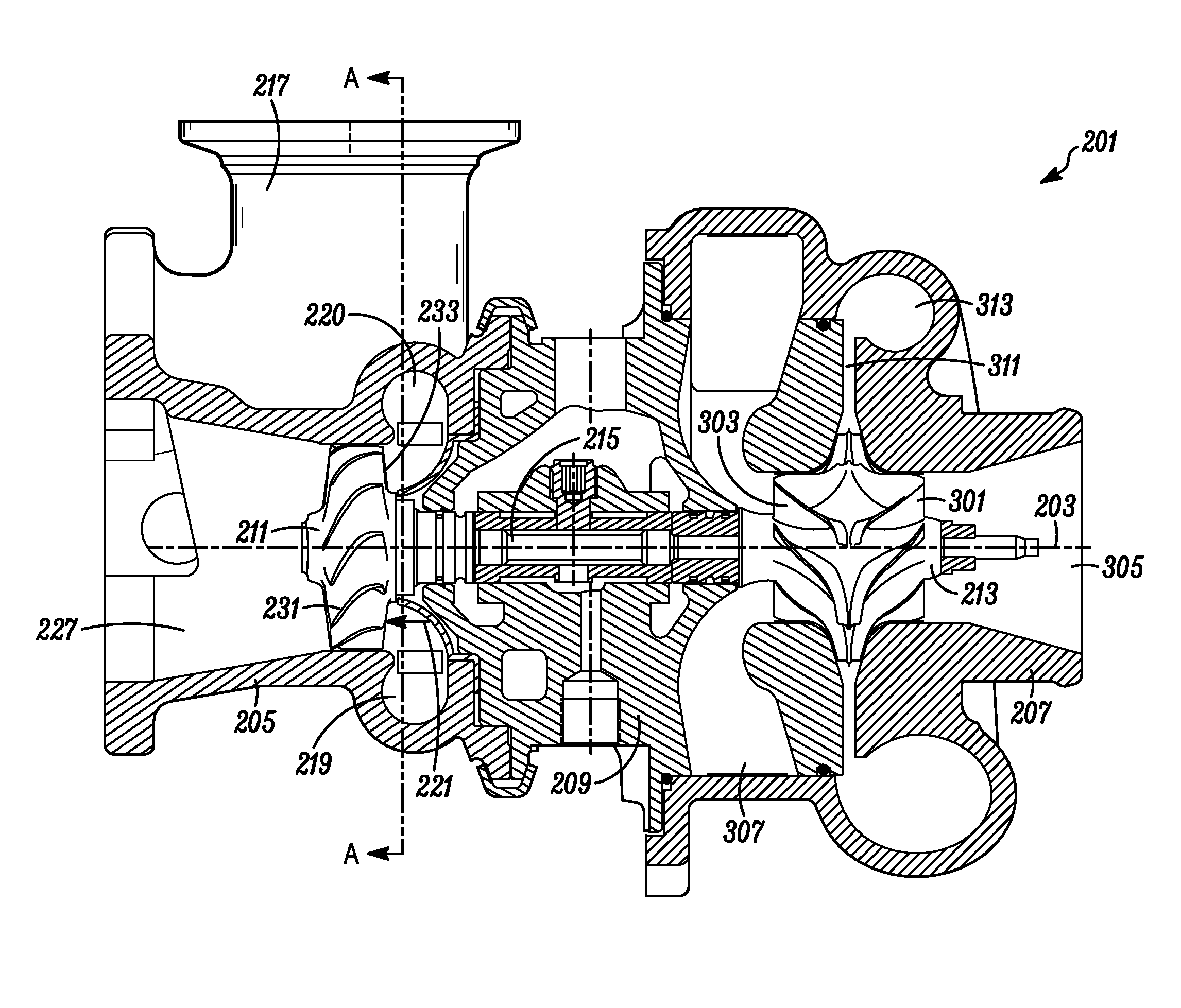
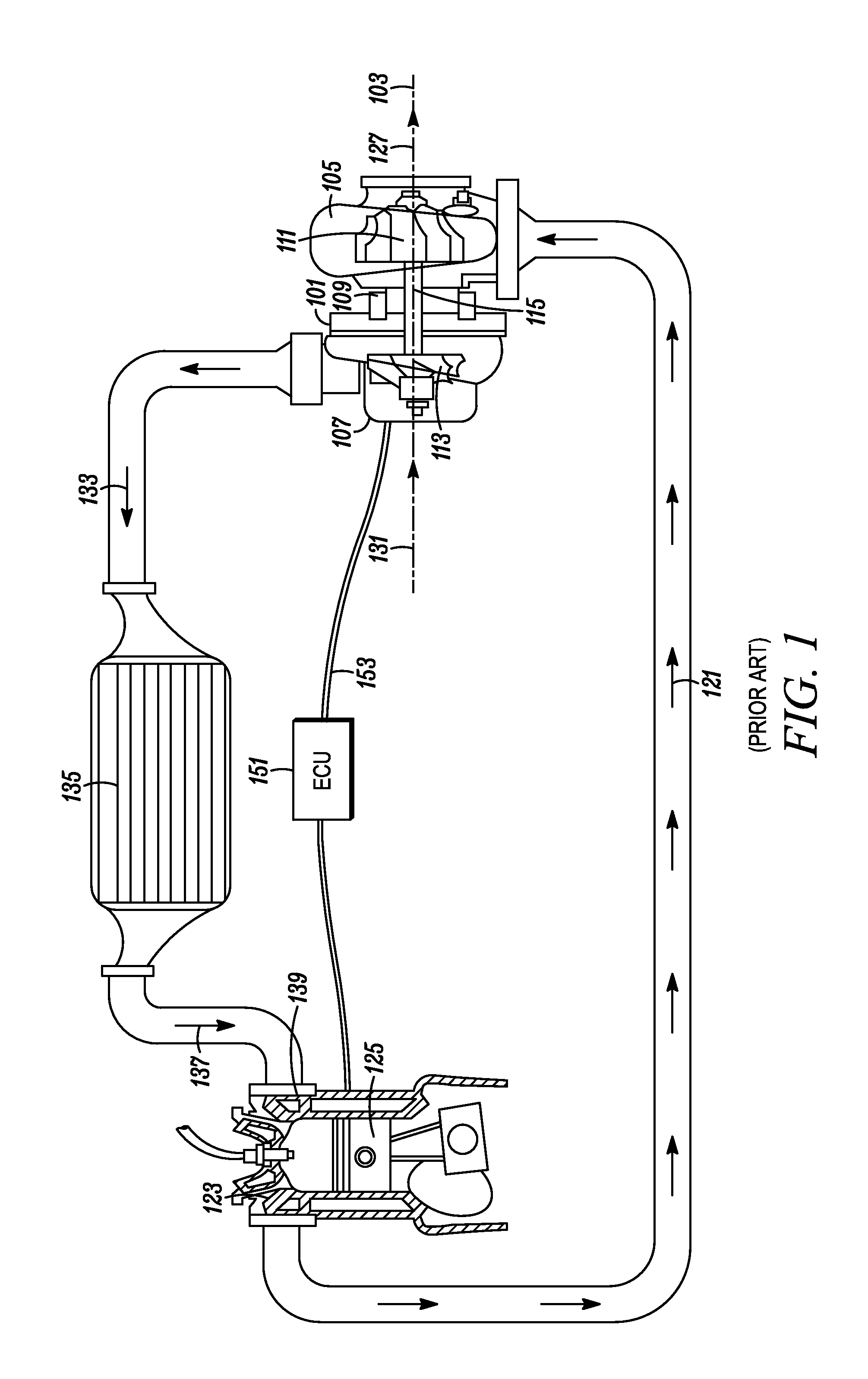
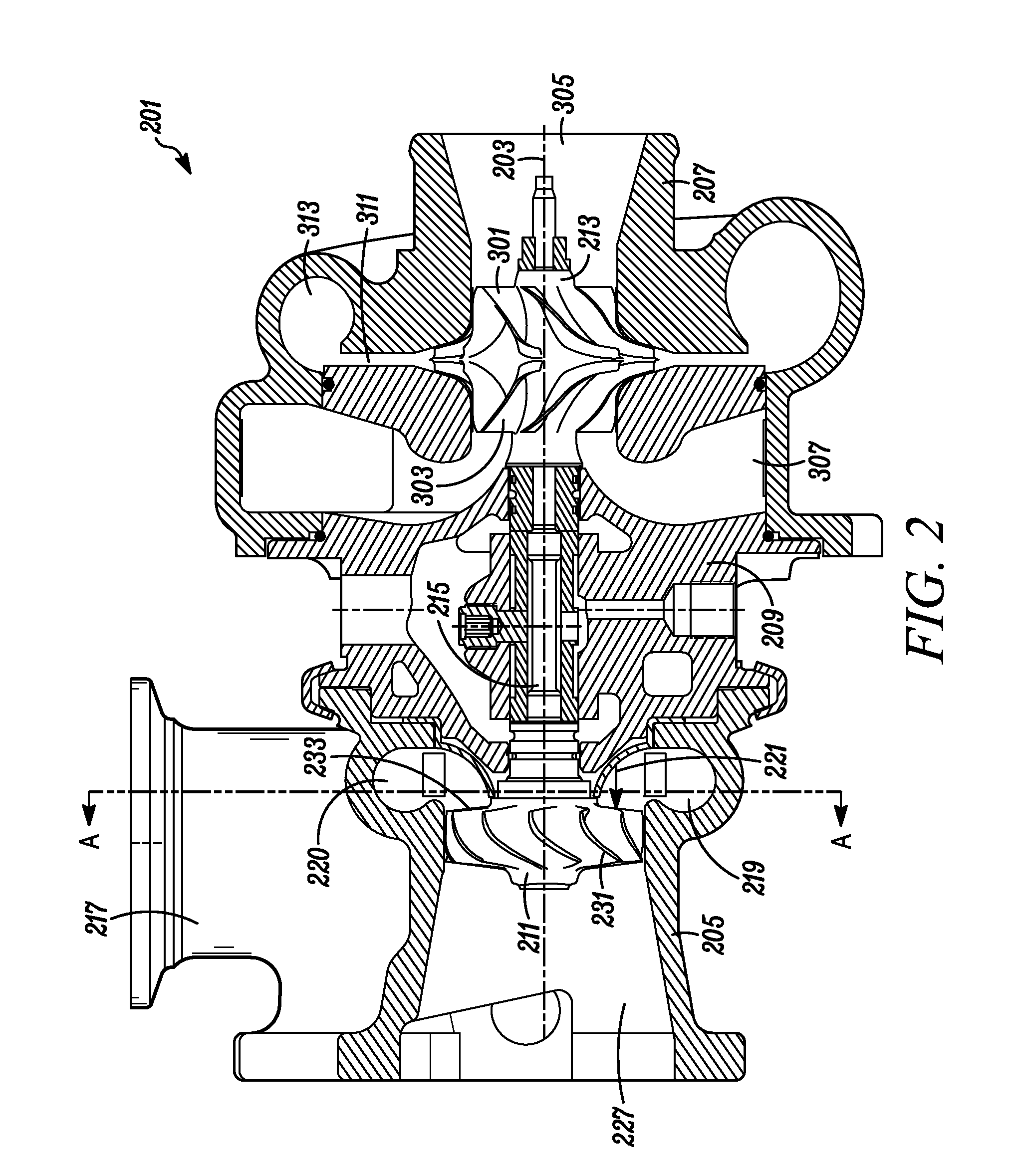
[0028]Typical embodiments of the present invention reside in a motor vehicle equipped with a gasoline powered internal combustion engine (“ICE”) and a turbocharger. The turbocharger is equipped with a unique combination of features that may, in various embodiments, provide the aerodynamic benefits of a zero reaction turbine with the geometric benefits of a fifty percent reaction turbine, and / or provide significantly improved system efficiencies by combining less efficient components in a manner that redu...


PUM


Abstract

A turbocharger including a turbine wheel having a hub-to-tip ratio of no more than 60% and blades with a high turning angle, a turbine housing forming an inwardly spiraling primary-scroll passageway that significantly converges to produce highly accelerated airflow into the turbine at high circumferential angles, and a two-sided parallel compressor. The compressor and turbine each produce substantially no axial force, allowing the use of minimal axial thrust bearings.

Description

[0001]The present invention relates generally to turbochargers and, more particularly, to an axial turbine having radial variable nozzle turbine vanes.BACKGROUND OF THE INVENTION[0002]With reference to FIG. 1, a typical turbocharger 101 having a radial turbine includes a turbocharger housing and a rotor configured to rotate within the turbocharger housing along an axis of rotor rotation 103 on thrust bearings and two sets of journal bearings (one for each respective rotor wheel), or alternatively, other similarly supportive bearings. The turbocharger housing includes a turbine housing 105, a compressor housing 107, and a bearing housing 109 (i.e., a center housing that contains the bearings) that connects the turbine housing to the compressor housing. The rotor includes a turbine wheel 111 located substantially within the turbine housing, a compressor wheel 113 located substantially within the compressor housing, and a shaft 115 extending along the axis of rotor rotation, through th...

Claims


Application Information

Patent Timeline
Patent Type & Authority Applications(United States)
IPC IPC(8): F04D25/04
CPCF04D25/04F01D9/026F05D2220/40F01D5/021F01D17/165
Inventor KARES, VACLAVLOTTERMAN, JEFFREY ALLENFERDA, JOSEF
Owner HONEYWELL INT INC
Why Eureka
Try Eureka