
Flat field eyepiece

a flat field, eyepiece technology, applied in the field of eyepieces or magnifiers, can solve the problems of low yield, difficult and expensive manufacturing of eyepieces, and low yield of lens b>10/b>

Inactive Publication Date: 2010-09-28
EXCELIS INC
View PDF12 Cites 7 Cited by
  • Summary
  • Abstract
  • Description
  • Claims
  • Application Information

AI Technical Summary

Benefits of technology

The solution provides a cost-effective eyepiece / magnifier with a wide field of view greater than 55 degrees and modulation transfer function better than 50% at 40 line pairs / mm, while being easier to manufacture and reducing the risk of lens fractures, thus offering improved image quality and durability.

Problems solved by technology

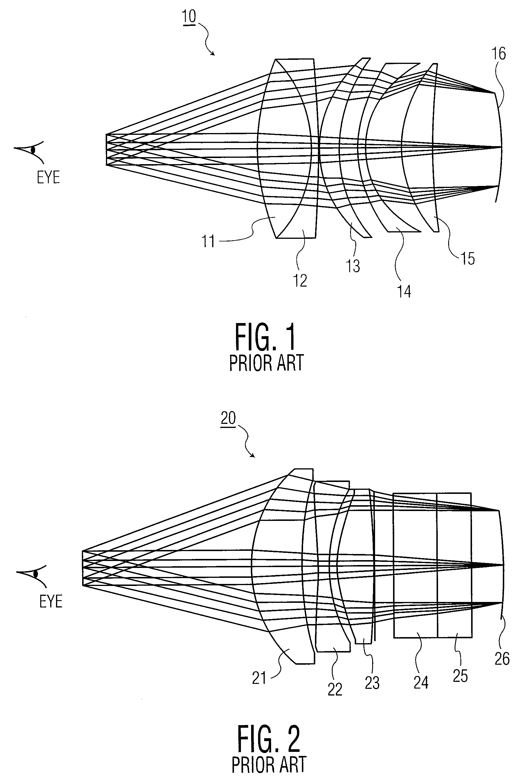
These eyepieces, however, are difficult and expensive to manufacture.
Due to the number of lenses and their curvatures, lens 10 is difficult and costly to manufacture.
Since lenses 13 and 14 are thin, they tend to fracture during manufacture, thereby resulting in low yields.
Lens 20 introduces harmonics, however, that result in multiple images unacceptable to a viewer.
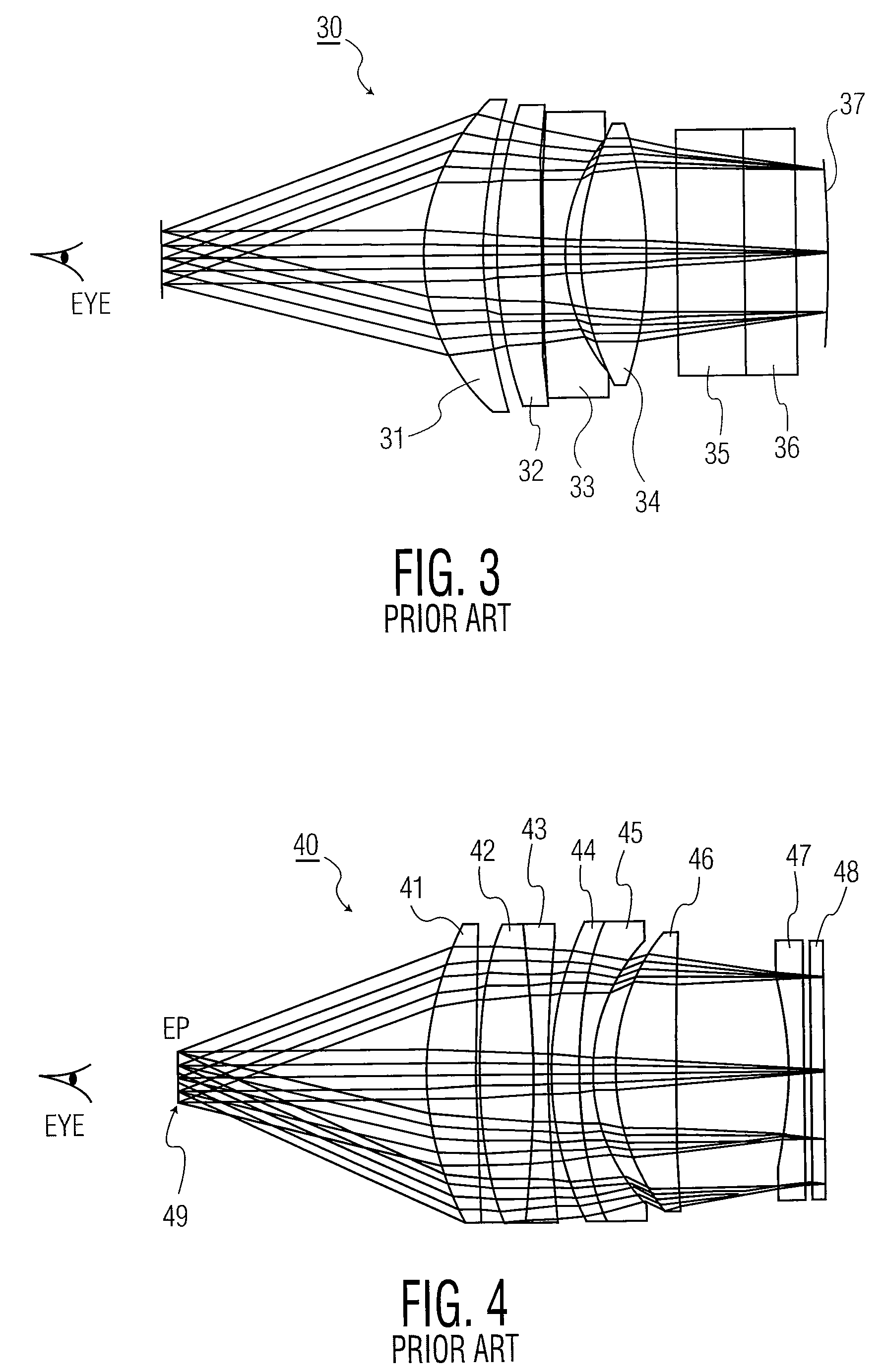
The lens 40 performs well but is expensive to produce.
As the field of view increases, or as a beam combiner is added, however, the eyepiece / magnifier becomes more complicated, resulting in a lens having five elements or more.
The eyepiece / magnifier, thus, results in a complex and expensive design, without good fusing capability.

Method used


Image

  • Flat field eyepiece
  • Flat field eyepiece
  • Flat field eyepiece

Examples


Embodiment Construction

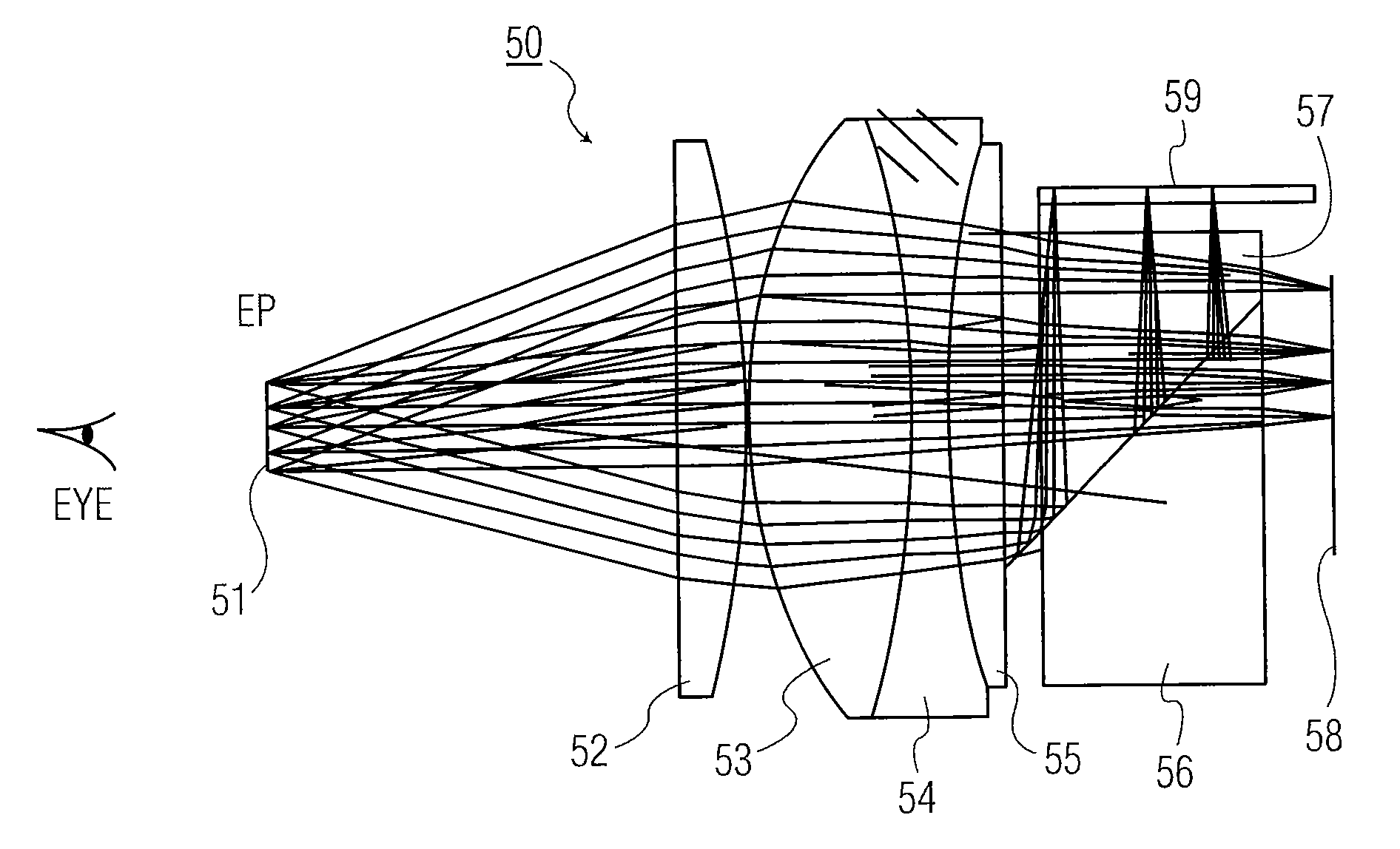
[0032]The present invention, as described below, provides a cost effective eyepiece / magnifier that may combine an image produced from a display with an image formed directly from an objective lens. The combined images may be projected toward a viewer with a wide field of view. In addition, the eyepiece / magnifier may be formed from individual lenses having no flat surfaces, no asphere surfaces and no diffractive surfaces. Furthermore, the eyepiece / magnifier may project a wide field of view from a flat or curved screen surface.

[0033]An embodiment of the present invention is shown in FIG. 5 as eyepiece / magnifier 50, sometimes also referred to herein as eyepiece 50 or magnifier 50. As shown, eyepiece 50 includes one glass triplet formed from three glass singlets, designated as 53, 54 and 55. Eyepiece 50 also includes a glass singlet, designated as 52, which is positioned between eye pupil 51 and the glass triplet. The image formed at eye pupil 51 is defined herein as an image formed at ...


PUM


Abstract

A lens system includes a first lens axially aligned with a second lens, where the first and second lenses are configured to be sequentially positioned from a pupil image of a viewer. The second lens is formed as a triplet having three cemented elements. The second lens includes a convex surface facing the first lens, and a flat surface opposing the convex surface of the second lens. The first lens includes a concave surface opposing a flat surface of the first lens; the second lens includes a concave surface and a convex surface; and the concave surface of the first lens and the concave and convex surfaces of the second lens have equal radii of curvatures.

Description

FIELD OF THE INVENTION[0001]The present invention relates, in general, to an eyepiece or magnifier and, more particularly, to an eyepiece or magnifier used in night vision goggle systems and head mounted displays.BACKGROUND OF THE INVENTION[0002]Night vision goggles and head mounted displays require eyepieces or magnifiers that are color corrected for red, green and blue, with high image quality having modulation transfer functions (MTFs) greater than 50% at 40 line pairs per millimeter (lp / mm). These eyepieces or magnifiers cooperate with displays or screens of image tubes to bring images to the eyes of viewers. These eyepieces or magnifiers also require long eye relief greater than 20 mm, so that a viewer may have more tolerance in positioning his eyes to view an image.[0003]A good eyepiece / magnifier must be insensitive to the position of the eye, because in a magnifier there is no exit-pupil-image of an objective lens to define the location of a user's eye. This requires a better...

Claims


Application Information

Patent Timeline
Patent Type & Authority Patents(United States)
IPC IPC(8): G02B25/00
CPCG02B9/06G02B25/001G02B25/00
Inventor JANECZKO, DONALDHALL, JOHN MICHAEL
Owner EXCELIS INC
Learn More