
Dual-axis planar motor providing force constant and thermal stability

a planar motor and force constant technology, applied in the direction of dynamo-electric machines, electrical apparatus, magnetic circuits, etc., can solve the problems of thermal drift, inconvenient component replacement, inaccurate positioning operation of the planar motor along the two axes of motion, etc., and achieve the effect of reducing thermal dri

Active Publication Date: 2010-10-05
ASM ASSEMBLY AUTOMATION LTD
View PDF11 Cites 33 Cited by
  • Summary
  • Abstract
  • Description
  • Claims
  • Application Information

AI Technical Summary

Benefits of technology

[0006]It is thus an object of the invention to seek to provide a planar motor with thermal stability which is capable of generating motion along two axes simultaneously while minimizing changes to the force constant as well as reducing thermal drift.

Problems solved by technology

This form of planar motor needs two separate sets of coils and magnets, which is therefore not cost-effective in terms of the components required.
When the planar motor runs for a prolonged period, the mechanical components expand and cause thermal drift.
This results in inaccurate positioning operation of the planar motor along the two axes of motion.
This ultimately affects the positioning control performance of the planar motor.
Furthermore, the temperature of the planar motor cannot be kept constant which results in thermal drift and contributes to inaccurate positioning control.

Method used


Image

  • Dual-axis planar motor providing force constant and thermal stability
  • Dual-axis planar motor providing force constant and thermal stability
  • Dual-axis planar motor providing force constant and thermal stability

Examples


Embodiment Construction

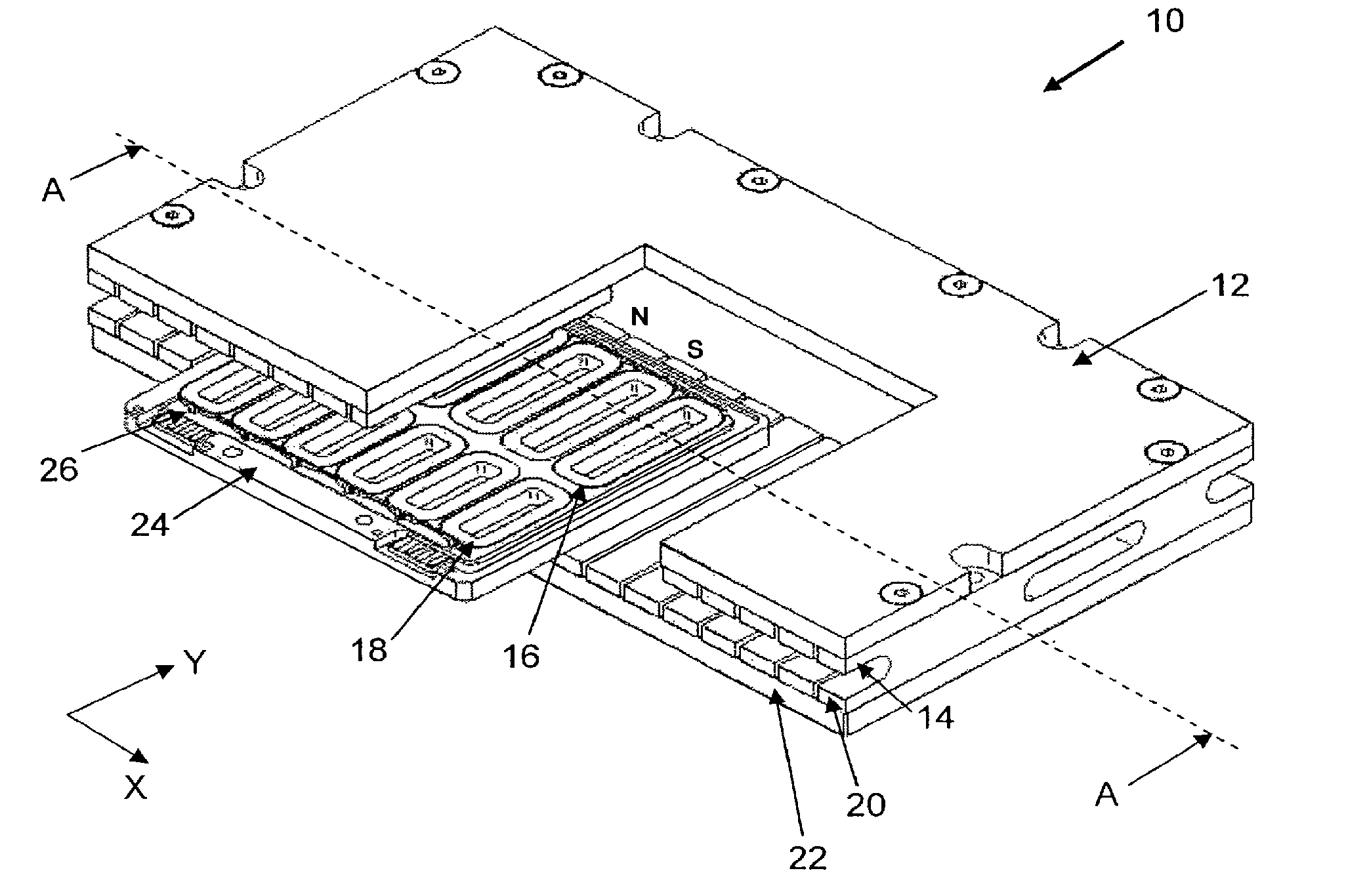
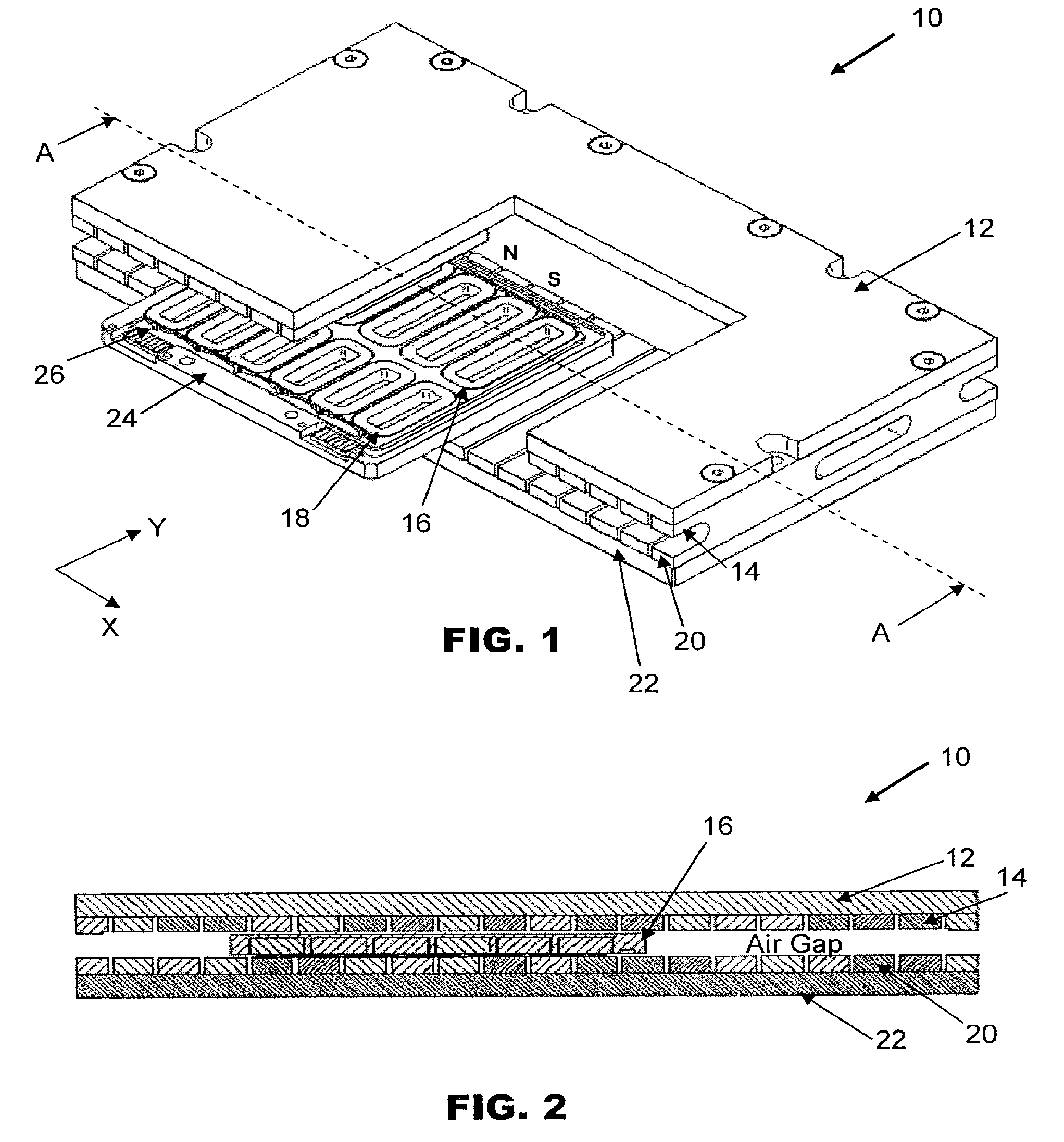
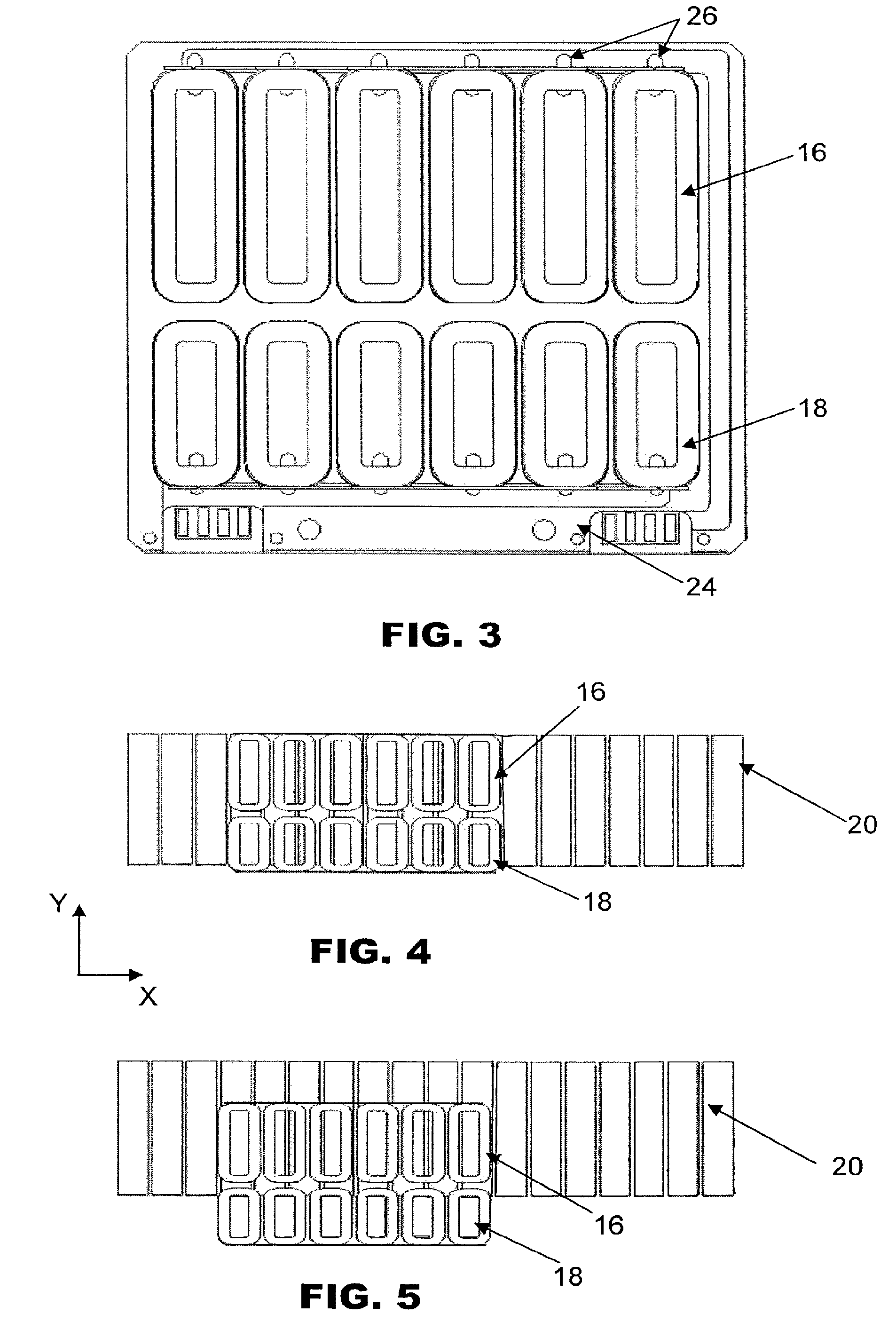
[0015]FIG. 1 is an isometric view of a multi-phase planar motor 10 according to the preferred embodiment of the invention with a portion of a top mount 12 and a first row of magnets 14 removed to reveal first and second sets of coils 16, 18 of a coil bracket 24. The planar motor10 generally comprises the coil bracket 24 and a magnet assembly. The magnet assembly has first and second rows of magnets 14, 20 arranged along a first or X-axis and separated by a gap for generating magnetic flux lines between the rows of magnets. The first row of magnets 14 is mounted on the top mount 12 and the second row of magnets 20 is mounted on a bottom mount 22. Each row of magnets 14, 20 forms a continuous permanent magnetic track along the length of the top mount 12 and bottom mount 22 for guiding the movement of the coil bracket 24 located within the gap between the two rows of magnets 14, 20.

[0016]The first set of coils 16 is arranged along the X-axis corresponding to the length of the top and b...


PUM


Abstract

A motor is provided comprising a magnet assembly having two rows of magnets arranged along a first axis, which are separated by a gap for generating magnetic flux lines between the rows of magnets. The motor further comprises a coil bracket which is located within the gap between the two rows of magnets. The coil bracket includes a first set of coils arranged along the first axis that are operative to drive movement of the coil bracket relative to the magnet assembly along the first axis. A second set of coils arranged along the first axis are operative to drive movement of the coil bracket relative to the magnet assembly along a second axis which is orthogonal to the first axis between a first end position and a second end position along the second axis. The first set of coils is fully located within the flux lines generated by the magnet assembly at both the first and second end positions of the coil bracket and the second set of coils is located at least partially outside the flux lines generated by the magnet assembly at the second end position of the coil bracket.

Description

FIELD OF THE INVENTION[0001]The invention relates to motors for positioning objects, and in particular to a planar motor which provides at least two degrees of freedom.BACKGROUND AND PRIOR ART[0002]Multi-phase linear electromagnetic motors generally comprise a row of permanent magnets to generate magnetic flux. Induction coils or phase coils are arranged facing the magnets and in directions that are transverse to the flux lines generated by the magnets. A typical multi-phase linear motor for driving a motion stage may have two or three coils arranged longitudinally, in such a way as to be arranged in line with the motion directions of the motion stage. Hence, the coils are arranged parallel to the motion direction. In a two-phase motor where there are two sets of phase coils, the two phase currents are mutually offset by 90°. In a three-phase motor, the three phase currents are mutually offset by 120°.[0003]A planar motor which comprises linear drivers may drive motion along two cho...

Claims


Application Information

Patent Timeline
Patent Type & Authority Patents(United States)
IPC IPC(8): H02K41/02
CPCH02K41/03H02K2201/18
Inventor WIDDOWSON, GARY PETERGAN, WAI CHUEN
Owner ASM ASSEMBLY AUTOMATION LTD
Learn More