Disk drive load arm structure having a strain sensor and method of its fabrication

a technology of strain sensor and load arm, which is applied in the direction of contact members penetrating/cutting insulation/cable strands, instruments, record information storage, etc., can solve the problem that the design of the load beam has become more complex

Active Publication Date: 2010-10-12
SEAGATE TECH LLC
View PDF31 Cites 36 Cited by
  • Summary
  • Abstract
  • Description
  • Claims
  • Application Information

AI Technical Summary

Problems solved by technology

Another source of deformations is windage, which is movement of the load beam or head suspension assembly due to airflow forces.
As performance and resonant frequency requirements have become more stringent, load beam designs have become more complex, as have the methods of forming the load beams.

Method used


Image

  • Disk drive load arm structure having a strain sensor and method of its fabrication
  • Disk drive load arm structure having a strain sensor and method of its fabrication
  • Disk drive load arm structure having a strain sensor and method of its fabrication

Examples


Embodiment Construction

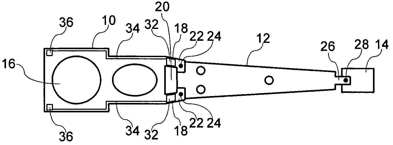
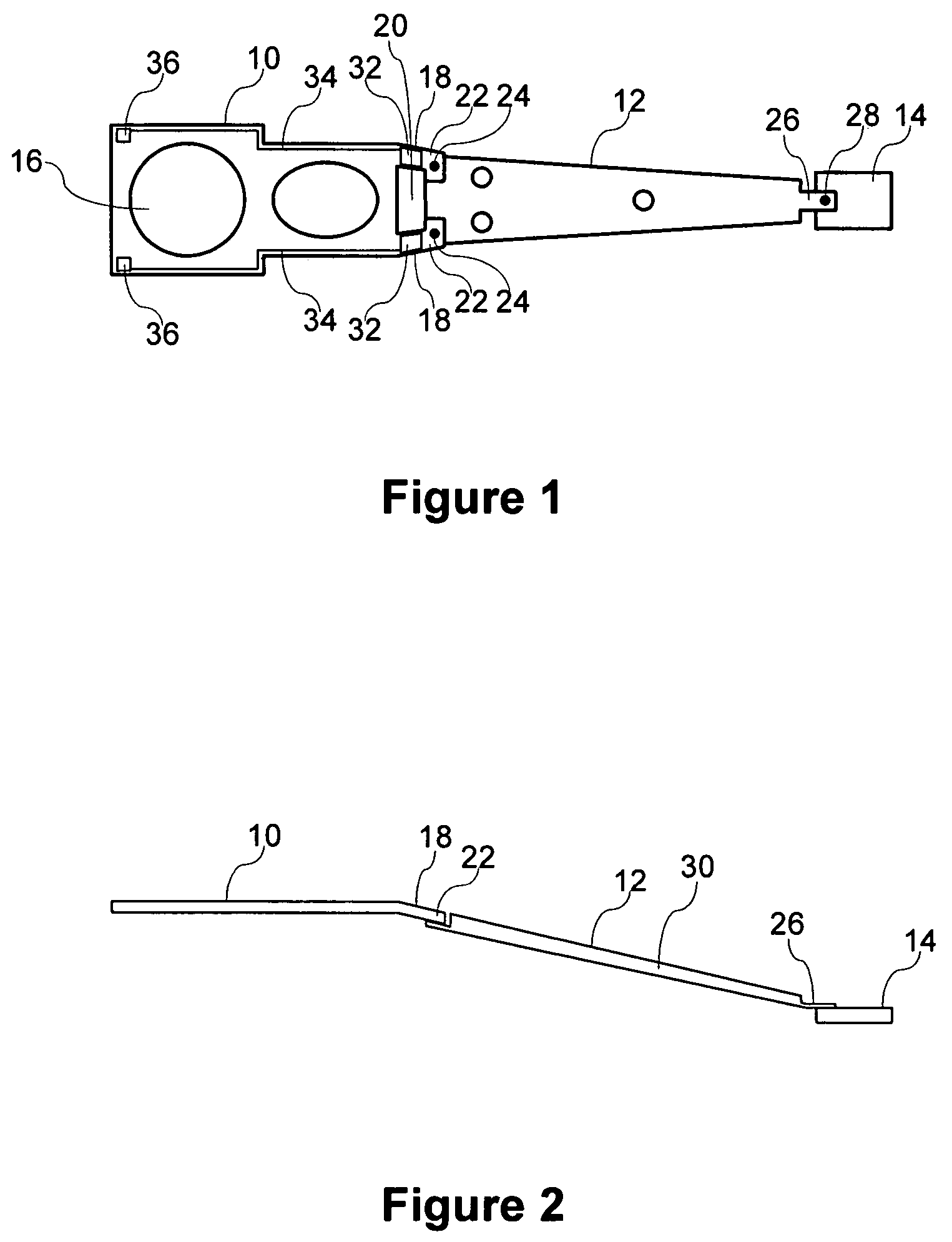
[0025]In accordance with one embodiment, a load beam is comprised of a base section, an arm section and a head suspension assembly that are fabricated separately and joined to form a load beam. FIG. 1 shows an example of such a load beam. The load beam is comprised of a base section 10, an arm section 12, and a head suspension assembly 14. Each section is made of steel or another material having appropriate strength and workability. The base section 10 is mountable to an actuator arm of a hard disk drive voice coil motor, and is provided with an opening 16 for receiving a spindle of the voice coil motor. At a distal end, the base section 10 has a pair of hinge arms 18 separated by an opening 20. The width of the opening is chosen to provide a desired spring factor for the hinge arms 18. At the end of the hinge arms 18 are tabs 22 that serve as welding points for spot welds 24 that join the arm section 12 to the base section 10. The arm section 12 has a tab 26 at its distal end that ...


PUM

PropertyMeasurementUnit
mechanical deflectionaaaaaaaaaa
lengthaaaaaaaaaa
piezoelectricaaaaaaaaaa

Abstract

A load arm for a disk drive may include a base section that has an opening for receiving a spindle of a voice coil motor. The base section may have hinge arms that extend from the base section and terminate in tab portions. An arm section may be affixed to the tabs of the hinge arms of the base section such as by spot welding. A head suspension assembly may be affixed to a distal end of the arm section such as by spot welding. A sensor may be provided on a hinge arm of the base section. The sensor may comprise a piezoelectric polymer sensing element and an electrode formed over the piezoelectric polymer sensing element.

Description

RELATED APPLICATIONS[0001]This application claims priority from U.S. Provisional Patent Application 60 / 759,808, filed Jan. 18, 2006, the entirety of which is incorporated herein by reference.BACKGROUND[0002]1. Field of the Invention[0003]Embodiments relate to hard disk drives, and specifically to a suspension assembly for supporting the moveable head of a hard disk drive.[0004]2. Related Art[0005]Disk drive storage systems typically include a plurality of magnetic storage medium disks stacked on a rotatable spindle and a corresponding number of magnetic heads that read binary digital information from and write binary digital information to the disks. The heads are typically supported by an actuator assembly. The actuator assembly normally includes a voice coil motor that causes pivotal motion of an actuator arm about an axis. A load beam is attached to the actuator arm and extends outward from the actuator arm over a disk surface. The load beam typically includes a base section that...

Claims


Application Information

Patent Timeline
Patent Type & Authority Patents(United States)
IPC IPC(8): G11B21/02
CPCG11B5/4813G11B5/5552
Inventor GUO, WEIXU, YANCHUTIAN, JIFANG
Owner SEAGATE TECH LLC
Why Eureka
Try Eureka