Apparatus for the continuous filtering of impurities from a flowable compound

a technology of flowable compound and filter, which is applied in the direction of moving filter element filter, filtration separation, separation process, etc., can solve the problems of affecting the quality of the filter, etc., so as to achieve rapid and smooth exchange of filters, easy mounting or dismounting, and special easy and cost-effective effects

Active Publication Date: 2010-10-26
SCHULZ KATHARINA
View PDF18 Cites 7 Cited by
  • Summary
  • Abstract
  • Description
  • Claims
  • Application Information

AI Technical Summary

Benefits of technology

[0007]The relevant advantage of the invention is that a filter insert arranged in accordance with the invention can be mounted or dismounted easily in the housing and that such disk-like filters can be produced especially easily and cost-effectively. These disk-like filters can be provided with an integral arrangement or in several parts, are fastened to the filter support arranged as a rotary body and the filter insert is then inserted into the housing. The filters are mounted by means of screwed joints or suitable clamping apparatuses on the support body. It is principally possible to have the filter insert rotate against the discharge apparatus in the housing. It can optionally also be provided to arrange the discharge apparatus to rotate about the rotational axis of the rotary body. Since the filters are always directly exposed and accessible as a result of their design after opening the housing, the invention always enables a rapid and smooth exchange of filters. There is no likelihood of any gluing of the filter insert in the housing after a curing of the plastic melt which would have a strong influence on the removal of the filter insert from the housing.
[0008]The simplest of constructional conditions are obtained when the filter insert is held in a rotationally driven way in the housing with a disk plane arranged perpendicular to the rotational axis of the rotary body. The discharge apparatus cooperates with the filter in such a way that the filter surface is continuously moved past the discharge apparatus as a result of the rotary drive, with impurities retained by the filter being removed continuously from the apparatus by the discharge apparatus.
[0009]In order to increase the cleaning effect of the discharge apparatus, it can comprise at least one scraper which is arranged behind the feed screw in the direction of rotation of the filter insert and pressed against the filter, this being in addition to the at least one feed screw which is arranged with its rotational axis preferably parallel to the disk plane. It is possible to provide both one scraper and / or discharge screw as well as several thereof, which combine with each other to form the discharge apparatus. The direction of rotation of the discharge screw can either be in the same direction relative to the direction of rotation of the filter insert or in the opposite direction thereof, depending on the operational conditions.
[0010]When the feed conduit for the compound to be filtered opens into a ring conduit which guides the filtrate to the filter and tapers towards the filter in the direction of rotation of the filter insert, i.e. in the direction of rotation towards the feed screw, it is ensured that always the largest possible filtering surface area is available for filtering and an increased filtering pressure on the filter and thus a certain forced pressing of the compound through the filter is ensured by the rotational movement of the filter insert against the ring conduit and as a result of the frictional forces prevailing between filter, compound and ring conduit.
[0011]In order to enable performing a rapid change of filters, it is recommended to arrange the housing with at least two housing parts that are detachably connected with each other, with one housing part receiving the filter insert and the other housing part the discharge apparatus. The two housing parts can be separated rapidly from each other by opening the locking elements, whereupon all parts subject to wear and tear are directly exposed for servicing purposes. The filters can then be exchanged or serviced, optionally without having to remove the filter insert. Moreover, the other housing part with the scraper and the discharge screw can be serviced in a simple way because the individual components are already accessible directly after the separation of the two housing parts and need not be removed in a cumbersome way.
[0012]The screw arranged parallel to the filter disk receives the material scraped off by the scraper and guides it out of the housing. The screw can be provided with a large variety of profiles. Optionally, the screw itself is arranged as a scraper and, in order to ensure sufficient scraping effect, is arranged with increased lead and optionally with multiple threads. A screw with a scraper edge with a scraping angle of 90° for example is mentioned here by way of example.

Problems solved by technology

An aggravating factor is that the degree of contamination with impurities can be very high, which substantially increases the cleaning effort and obviously places a considerable burden on the provided filters.
The disadvantageous aspect in this known construction is that it is difficult after a filtering process to remove the filter insert from the housing with the usual tools, as is regularly required for the purpose of a repair or a replacement.
Such an exchange is mostly only possible with much effort, with the filter insert usually being destroyed.
A further disadvantage is that for servicing such apparatuses one must accept relatively long standstill periods and that such filters are comparatively expensive.

Method used


Image

  • Apparatus for the continuous filtering of impurities from a flowable compound
  • Apparatus for the continuous filtering of impurities from a flowable compound
  • Apparatus for the continuous filtering of impurities from a flowable compound

Examples


Embodiment Construction

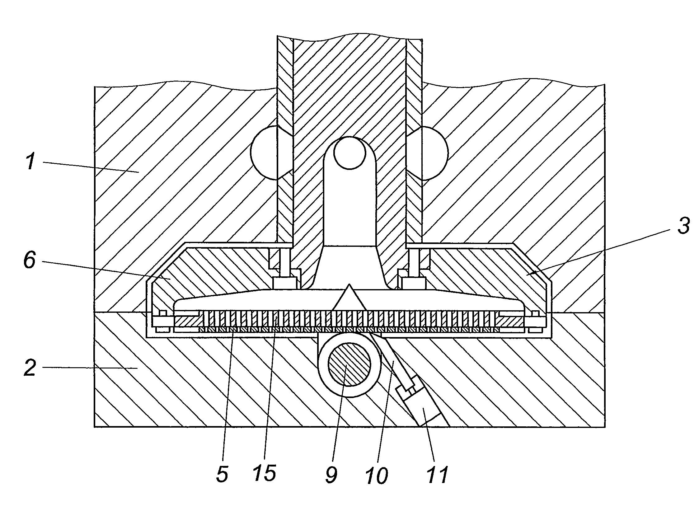
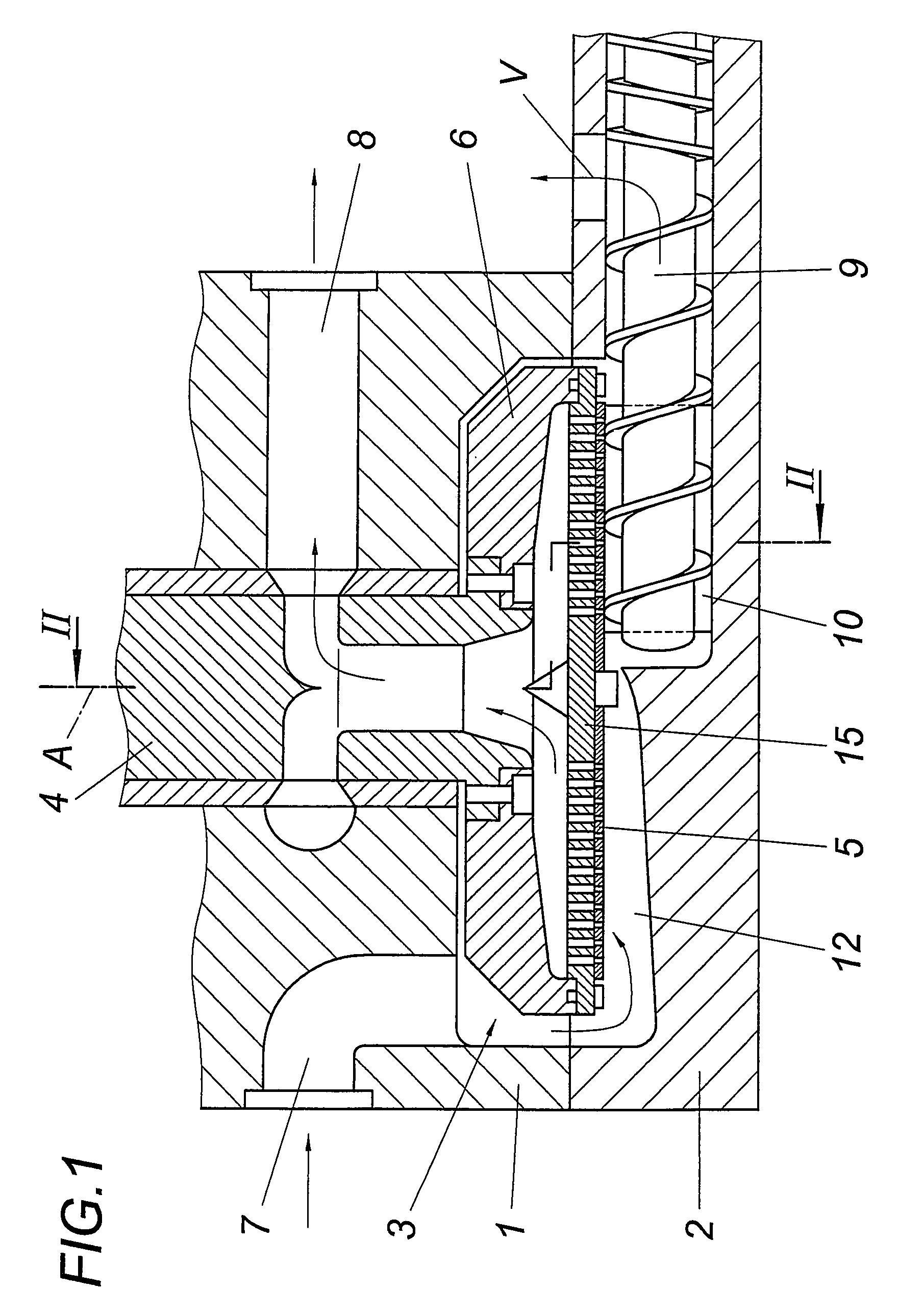
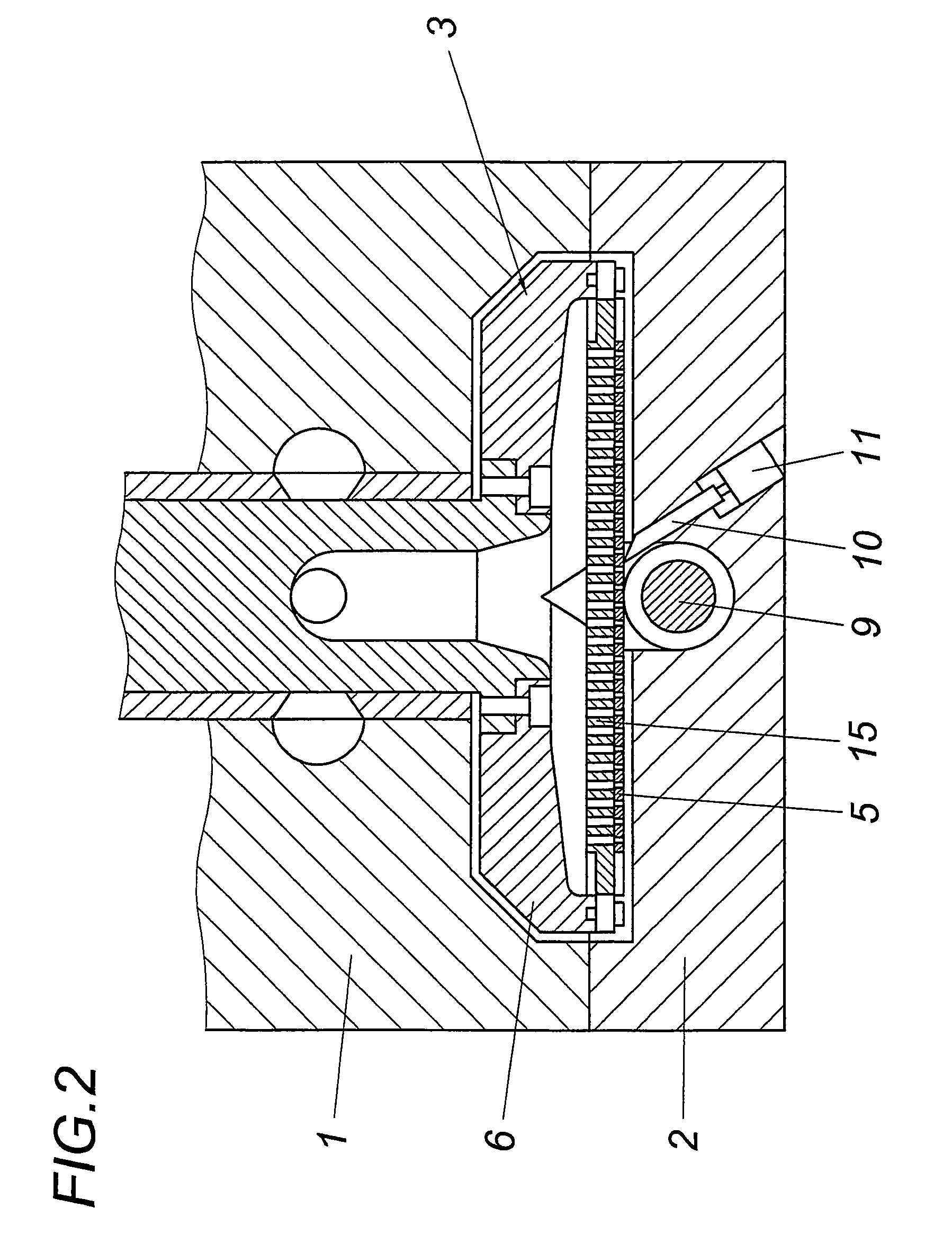
[0017]An apparatus for the continuous filtering of impurities from a contaminated flowable compound, especially a plastic melt, comprises a housing with two housing halves 1, 2, in which a filter insert 3 is provided in the form of a hollow rotary body which is held in a rotatable manner about its rotational axis A relative to the housing 1, 2 and is flowed through by the flowable manner. Filter insert 3 comprises a filter shaft 4 and a ring disk 6 which is fixed at the end side to the filter shaft 4 and receives a filter disk 5 mounted on a support 15. The filter disk 5 which is arranged on the support 15 is screwed together with the support 15 and ring disk 6, respectively, as also the ring disk 6 with the filter shaft 4. The ring disk 6 and the filter shaft 4 are provided with a hollow arrangement in order to enable the flow of filtered plastic material through the same.

[0018]Filter insert 3 is arranged in a flow conduit of the housing 1, 2 between a feed conduit 7 for the compou...


PUM

PropertyMeasurementUnit
scraping angleaaaaaaaaaa
specific densitiesaaaaaaaaaa
sizeaaaaaaaaaa

Abstract

The invention relates to an apparatus for the continuous filtering of impurities from a flowable compound, especially a plastic melt, comprising a filter insert (3) in the form of a hollow rotary body which is held to rotate about its rotational axis (A) relative to a housing (1, 2) and is flowed through by the flowable compound and which is arranged in a flow conduit of the housing (1, 2) between a feed conduit (7) for the compound to be filtered and a discharge conduit (8) for the filtered compound, and a discharge apparatus for impurities held back by the filter, which apparatus comprises a feed screw (9) cooperating with the filter insert (3). In order to provide advantageous constructional conditions it is proposed that the filter insert (3) comprises a disk-like filter (5) which is arranged on the face side of the rotary body and is coaxial to the rotational axis (A).

Description

CROSS REFERENCE TO RELATED APPLICATIONS[0001]This application is the National Stage of PCT / AT2007 / 000431 filed on Sep. 12, 2007, which claims priority under 35 U.S.C. §119 of Austrian Application No. A 1521 / 2006 filed on Sep. 13, 2006. The international application under PCT article 21(2) was not published in English.FIELD OF THE INVENTION[0002]The invention relates to an apparatus for the continuous filtering of impurities from a flowable compound, especially a plastic melt, comprising a filter insert in the form of a hollow rotary body which is held to rotate about its rotational axis relative to a housing and is flowed through by the flowable compound and which is arranged in a flow conduit of the housing between a feed conduit for the compound to be filtered and a discharge conduit for the filtered compound, and a discharge apparatus for impurities held back by the filter, which apparatus comprises a feed screw cooperating with the filter insert.DESCRIPTION OF THE PRIOR ART[0003...

Claims


Application Information

Patent Timeline
Patent Type & Authority Patents(United States)
IPC IPC(8): B01D33/46B01D33/70B29C48/03B29C48/55B29C48/693B29C48/70
CPCB01D33/15B29C47/683B01D33/466B01D33/76B29C47/686B29C47/702B29C47/385B29C47/6037B29C47/0009B29C48/397B29C48/03B29C48/2735B29C48/55B29C48/6914B29C48/693B29C48/70Y02W30/62
Inventor SCHULZ, HELMUTH
Owner SCHULZ KATHARINA
Why Eureka
Try Eureka