Vortex-shedding-arrangement

a technology of shedding and arrangement, applied in the direction of motors, wind energy generation, engine fuctions, etc., can solve the problems of damage to the tower and its structural strength, severe danger to the mounting personal, damage to the transport equipment of the tower, etc., and achieve the effect of easy mounting and dismounting and extensive control

Active Publication Date: 2020-10-20
SIEMENS GAMESA RENEWABLE ENERGY AS
View PDF42 Cites 7 Cited by
  • Summary
  • Abstract
  • Description
  • Claims
  • Application Information

AI Technical Summary

Benefits of technology

[0014]An aspect relates to provide an improved Vortex-shedding-arrangement, which can be mounted and dismounted quite easily, and which does not need extensive control during the transportation.
[0024]Embodiments of the invention provide a temporarily mounted vortex shedding solution, which can be mounted on any tower quite easily with low efforts and costs.

Problems solved by technology

The tower may be segmented, due to its overall length and due to transport limitations.
The vortex induced vibrations might be strong enough to damage the tower and its structural strength.
The vortex induced vibrations may even damage the transport equipment of the tower, being an integrated part of the ship.
The vortex induced vibrations may even create trouble during the installation of the tower as the tower might start to swing and vibrate creating severe danger for the mounting personal.
The rope must be secured and controlled during the transportation, while the whole mount- and dismount-proceeding of the strake is complicated and time-consuming as well.
During erection of the wind turbine tower at site, the strakes also have a tendency to fall off which is not desirable and may cause the tower to start vibrate.
These vibrations complicate to a great extent mounting of the nacelle on top the tower.

Method used


Image

  • Vortex-shedding-arrangement
  • Vortex-shedding-arrangement
  • Vortex-shedding-arrangement

Examples


Embodiment Construction

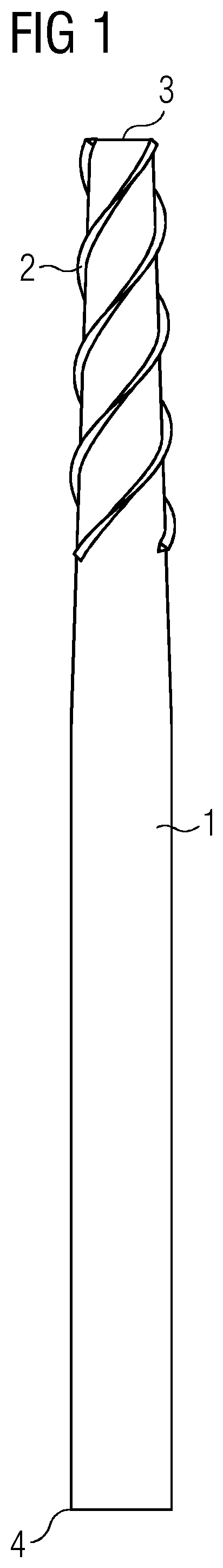
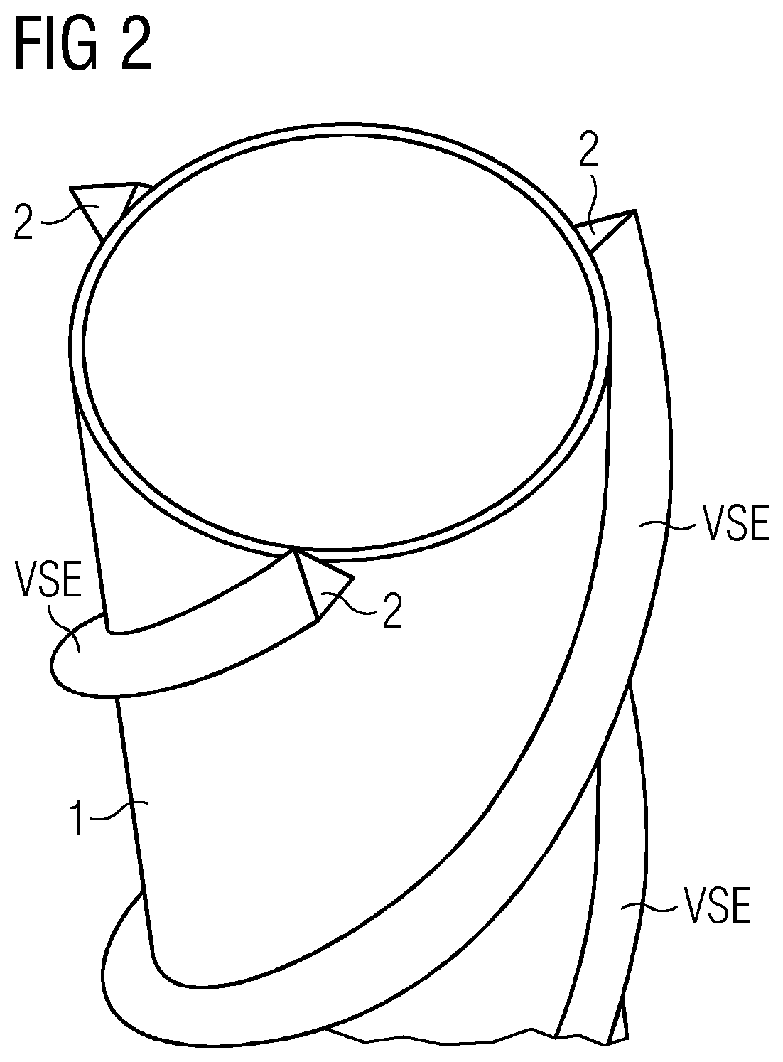
[0030]FIG. 1 shows a wind turbine tower 1 with an attached vortex shedding arrangement 2.

[0031]The vortex shedding arrangement 2 is shaped in a way that Vortex induced vibrations (VIV) during the installation and transportation of the wind turbine tower are reduced.

[0032]The wind turbine tower 1 comprises a top end 3 and a bottom end 4. The vortex shedding arrangement 2 is attached to the tower 1 from the top end 3 of the tower 1 towards the bottom end 4 of the tower 4.

[0033]The upper first third part of the length of the tower 1 is fitted with the vortex shedding arrangement 2.

[0034]A wind turbine tower 1, which is used for an offshore wind turbine installation site, is transported in an upright position from the harbor towards the installation site of the wind turbine by ship.

[0035]As described above strong wind is acting on the wind turbine tower 1, which starts to vibrate. The wind flows along the sides of the wind turbine tower 1 in a non-laminate structure. Thus, vortexes are ...


PUM

PropertyMeasurementUnit
angle of inclinationaaaaaaaaaa
angleaaaaaaaaaa

Abstract

A Vortex-shedding-arrangement, which is prepared to be arranged on a tower of a wind turbine, is provided. Embodiments of the invention even relate to a tower, which is equipped with the Vortex-shedding-arrangement and to a method to equip the tower with the Vortex-shedding-arrangement.The Vortex-shedding-arrangement according to embodiments of the invention is arranged and prepared to be connected to a surface of a tower. The Vortex-shedding-arrangement is prepared to reduce Vortex-induced-vibrations, acting on the tower and its structure, during the tower-transportation. The vortex shedding arrangement comprises vortex shedding elements and at least one shrink foil. The at least one shrink foil is prepared to fix and to position the vortex shedding elements at specific positions at the tower surface by heat applied to the shrink foil.

Description

CROSS-REFERENCE TO RELATED APPLICATIONS[0001]This application claims priority to PCT Application No. PCT / EP2017 / 077731, having a filing date of Oct. 30, 2017, which is based off of DE Application No. 10 2017 200 814.8, having a filing date of Jan. 19, 2017, and EP Application No. 16197511.5, having a filing date of Nov. 7, 2016, the entire contents all of which are hereby incorporated by reference.FIELD OF TECHNOLOGY[0002]The following relates to a Vortex-shedding-arrangement, which is prepared to be arranged on a tower of a wind turbine. Embodiments of the invention even relate to a tower, which is equipped with the Vortex-shedding-arrangement and to a method to equip the tower with the Vortex-shedding-arrangement.BACKGROUND[0003]A wind turbine comprises rotor blades, which are driven by the wind. The rotor-blades are connected via a turning hub with a nacelle. The turning rotor-blades drive an electrical generator via a so called main shaft. Generator and shaft are arranged in the...

Claims


Application Information

Patent Timeline
Patent Type & Authority Patents(United States)
IPC IPC(8): F03D13/10F15D1/12F03D13/20E04H12/00
CPCF03D13/10F03D13/20F15D1/12E04H12/00F05B2250/232F05B2230/40F05B2280/6012F05B2250/25F05B2240/912F05B2280/4003F05B2250/11F05B2230/90F05B2260/96F03D80/00Y02E10/72Y02E10/728
Inventor JENSEN, ANDERS HOEJRIS
Owner SIEMENS GAMESA RENEWABLE ENERGY AS
Why Eureka
Try Eureka