Pelvic bracing system

a pelvic bracing and pelvis technology, applied in the field of pelvic bracing system, can solve the problems of pain for patients, loss of control, and incompatible pelvis braces with many existing orthopedic joints, and achieve the effect of controlling the range of motion of the patient's hip join

Inactive Publication Date: 2006-08-01
HIPBOLT I P
View PDF6 Cites 43 Cited by
  • Summary
  • Abstract
  • Description
  • Claims
  • Application Information

AI Technical Summary

Benefits of technology

[0011]It is one object of this invention to provide a pelvic bracing system which provides circumferential and rotational support that is laterally and rotationally adjustable to properly fit a pelvic region and control the range of motion of the patient's hip joint via the metal joint connection with the thigh cuff.
[0012]It is another object of this invention to provide a thigh cuff that permits lateral and vertical adjustment relative to the patient's thigh.
[0019]An inner surface of the outer plate and an outer surface of the inner plate each has a fastening means, for example VELCRO brand hook and loop fastener or other similar fastening means. The inner surface is adjustably fastenable to the outer surface to securely connect the anterior portion of the first hip plate to the anterior portion of the second hip plate. The anterior panel provides circumferential support that aids in the function of the pelvic bracing system to provide stability and eliminate or reduce rotational and / or twisting motion of the pelvic bracing system.
[0023]The thigh cuff according to a preferred embodiment of this invention preferably forms an adjustable but rigid anchor for the pelvic bracing system and the articulating orthopedic joint. The thigh cuff is preferably adjustable both laterally and vertically, and as a result, possibly rotationally. This adjustment provides a custom fit which grabs the soft tissue of the thigh and obtains maximum control of leg movement, thereby fulfilling an objective of the pelvic bracing system according to a preferred embodiment of this invention.

Problems solved by technology

Such conventional pelvic braces demonstrate a considerable amount of twisting and / or rotation of the first hip brace with respect to the second hip brace resulting in discomfort for the patient and loss of control between the pelvic brace and a thigh cuff constraining the joint.
Thus, conventional pelvic braces are not compatible with many of the existing orthopedic joints.
Such an arrangement results in a considerable amount of twisting and / or rotation of the thigh cuff relative to the patient's thigh.

Method used


Image

  • Pelvic bracing system
  • Pelvic bracing system
  • Pelvic bracing system

Examples


Embodiment Construction

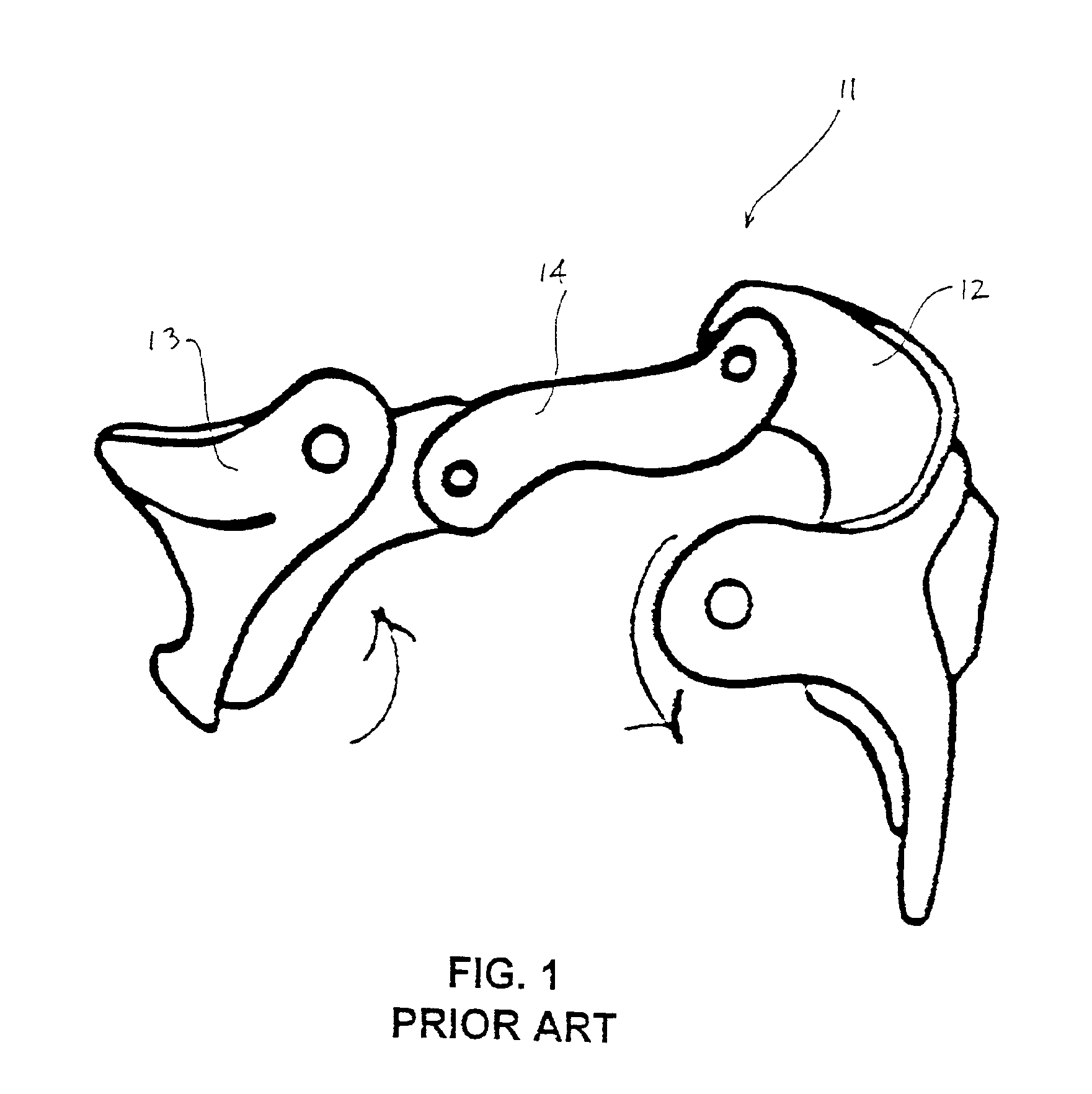
[0041]As described above, conventional pelvic braces generally have an open “C” configuration, with no circumferential support in the anterior portion of the pelvic brace. For example, as shown in FIG. 1, a conventional pelvic brace 11 has a first hip brace 12 connected to a second hip brace 13 by a posterior strap 14. Conventional pelvic brace 11 demonstrates a considerable amount of twisting and / or rotation of first hip brace 12 with respect to second hip brace 13. Thus, conventional pelvic brace 11 does not fit the patient comfortably, nor does conventional pelvic brace 11 provide adequate circumferential support to prevent twisting and / or rotation of hip braces 12 and 13 with respect to one another. Additionally, hip braces 12 and 13 of conventional pelvic brace 11 are not securely adjustable to properly fit the pelvic region to provide a comfortable fit for the patient.

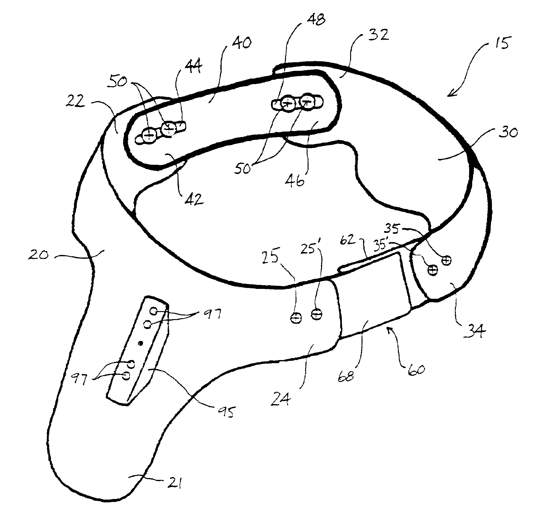
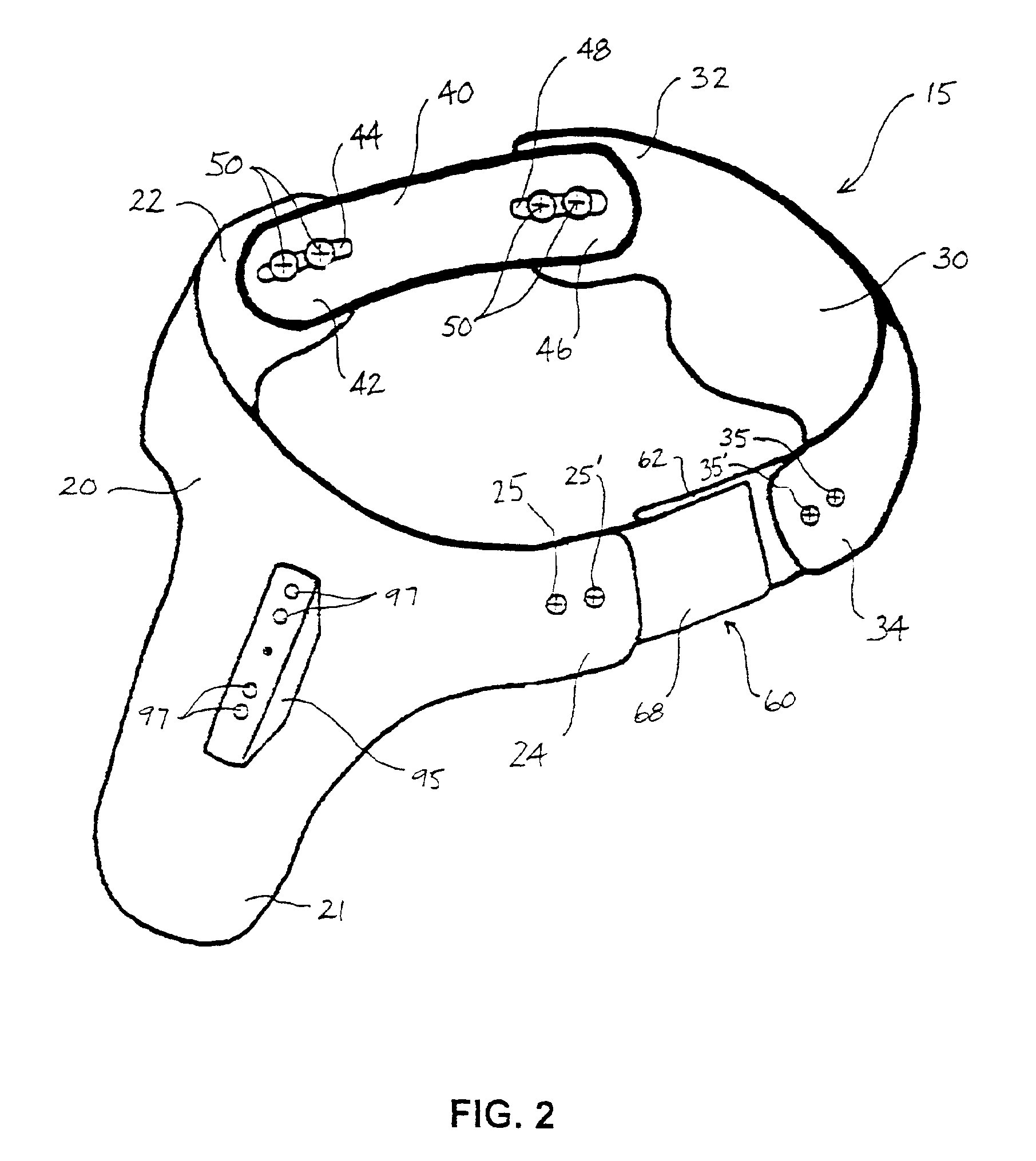
[0042]Conventional hip braces, as well as pelvic bracing system 15 according to this invention, typically incl...


PUM


Abstract

A pelvic bracing system having a first hip plate connected with respect to a second hip plate. The first hip plate and the second hip plate are laterally and / or rotationally adjustable with respect to a posterior panel to properly fit a posterior pelvic region of a patient. The first hip plate and the second hip plate are laterally and / or rotationally adjustable with respect to an anterior panel to properly fit an anterior pelvic region of the patient. In addition, a thigh cuff is connected with respect to the first hip plate or the second hip plate and is laterally and vertically adjustable across a first component and a second component.

Description

CROSS REFERENCE TO RELATED APPLICATION[0001]This application claims the benefit of U.S. patent application Ser. No. 09 / 489,599, issuing on 20 Nov. 2001 as U.S. Pat. No. 6,319,216, which claims the benefit of U.S. Provisional Application No. 60 / 116,645, filed 21 Jan. 1999, the disclosure of which earlier applications are hereby incorporated by reference herein and made a part hereof, including but not limited to those portions which specifically appear hereinafter.BACKGROUND OF THE INVENTION[0002]1. Field of the Invention[0003]This invention relates to a pelvic bracing system for use in post-operative rehabilitation and / or to combat the effects of chronic disease. More specifically, this invention relates to a pelvic bracing system having a posterior panel and an anterior panel for hip and waist adjustments, as well as for rotational and / or twisting stability, to provide a more comfortable and uniform fit for a patient.[0004]2. Description of Related Art[0005]Conventional pelvic brac...

Claims


Application Information

Patent Timeline
Patent Type & Authority Patents(United States)
IPC IPC(8): A61F5/00A61F5/02
CPCA61F5/028A61F5/0193
Inventor COLIGADO, JOSEPH
Owner HIPBOLT I P
Why Eureka
Try Eureka