Custom-fitted orthodontic bracket manufactured by computerized and selective removal of portions of a bracket

a technology of brackets and bracket brackets, applied in the field of custom-fitted orthodontic brackets, can solve the problems of affecting the proper articulation of language, and affecting the quality of life of the affected individual, and achieve the effect of less cost and better bracket and archwire positioning

Inactive Publication Date: 2006-01-24
ABELS NORBERT +1
View PDF22 Cites 39 Cited by
  • Summary
  • Abstract
  • Description
  • Claims
  • Application Information

AI Technical Summary

Benefits of technology

[0013]The foregoing problems with the prior state of the art are overcome by the principles of the present invention, which are directed towards methods for manufacturing custom-brackets that result in better bracket and archwire positioning without using rapid prototyping techniques. A three-dimensional digital representation of the current form of an orthodontic structure such as the teeth is used to identify portions of a bracket that should be removed. The identified bracket portion is then removed using any available mechanism such as precision laser or mechanical cutting. The bracket is formed by the removal of material, rather than the positive formation of material, and is thus a less costly and more timely way of manufacturing custom-fitted brackets.
[0014]In one embodiment, portions of the orthodontic bracket base are removed in order to allow for more precise fitting of the bracket to the tooth resulting in a stronger and more reliable bonding to the tooth. A computerized representation of an ideal orthodontic structure may be formed in order to automatically determine an ideal position of the bracket on the teeth. If the surface of the tooth is not spherical or close to spherical, then the orthodontist will be able to feel when the bracket has been correctly position thereby reducing the risk of bracket misplacement.
[0015]The correct position of the bracket is a function of the position of the archwire slot. In one embodiment, the archwire slot is already pre-manufactured within the bracket that is to have material cut away. However, that need not be the case. The computer may determine the ideal orientation of the archwire slot and the ideal position of the bracket on the tooth, and then cause the removal of appropriate material from the base and from the archwire slot to form a bracket that keys into the appropriate portion of the tooth while having an ideal and customized archwire slot. Since there is some flexibility in the positioning of the archwire slot, there is also some corresponding flexibility in the ideal placement of the bracket, which may be useful if there are some potential bracket placement positions that are less desirable than others. For example, the flexibility in the positioning of the archwire slot allows for some corresponding flexibility in how the archwire is bent. Accordingly, the archwire slot positions may be selected to allow for better hand-bending of the archwire.
[0017]On occasion, the surface of the tooth may be spherical or close to spherical making it very difficult, even when using custom-fitted brackets, for the orthodontist to feel when the bracket is keyed into the correct position. In that case, material may be removed from the bracket base such that there are one or more protrusions extending along the cut surface of the base from a permanent portion of the base. These protrusions extend to non-spherical surfaces and are thus helpful in keying the bracket into place. Once the brackets are affixed to the teeth, these protrusions may be removed thereby leaving only the permanent portion of the base. Accordingly, the orthodontist may use a sense of feel even when placing the bracket on substantially spherical surfaces of the tooth.

Problems solved by technology

Sever malformations or mechanical flaws of the individual's orthodontic structure may also interfere (even if only slightly) with the proper articulation of language.
Any degradation in these abilities may have a significant impact on the affected individual's quality of living.
Despite such expertise, however, while the teeth may generally move towards the corrected position, there may be some slight errors in the forces applied by the arched wire that become apparent from the path of movement of the teeth.
One problem associated with orthodontic brackets is that teeth can have a substantially infinite variety of curvatures.
Since there is only a limited number of bracket base curvatures to select, and an infinite variety of tooth surface curvatures, a perfect match is often elusive.
However, there are some disadvantages to this manufacturing technique.
Specifically, the positive formation of brackets using rapid prototyping techniques can be quite expensive and time-consuming.
Often orthodontists cannot afford rapid prototyping equipment so such manufacturing often needs to be performed by an off-site service.
In addition, the higher costs associated with rapid prototype manufacturing of brackets is most likely passed onto the patient (or insurer) thereby making custom-bracket use relatively expensive.

Method used


Image

  • Custom-fitted orthodontic bracket manufactured by computerized and selective removal of portions of a bracket
  • Custom-fitted orthodontic bracket manufactured by computerized and selective removal of portions of a bracket
  • Custom-fitted orthodontic bracket manufactured by computerized and selective removal of portions of a bracket

Examples


Embodiment Construction

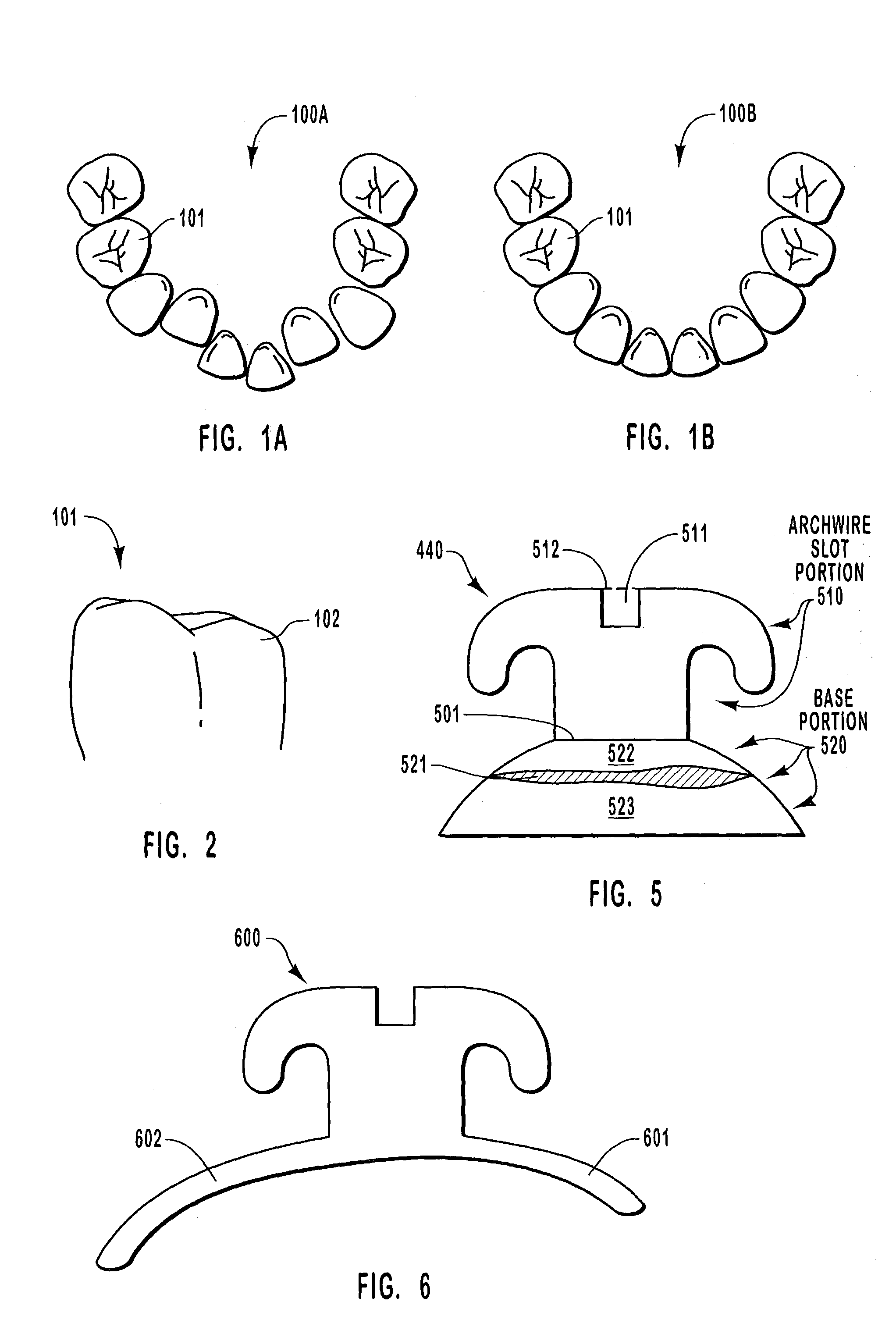
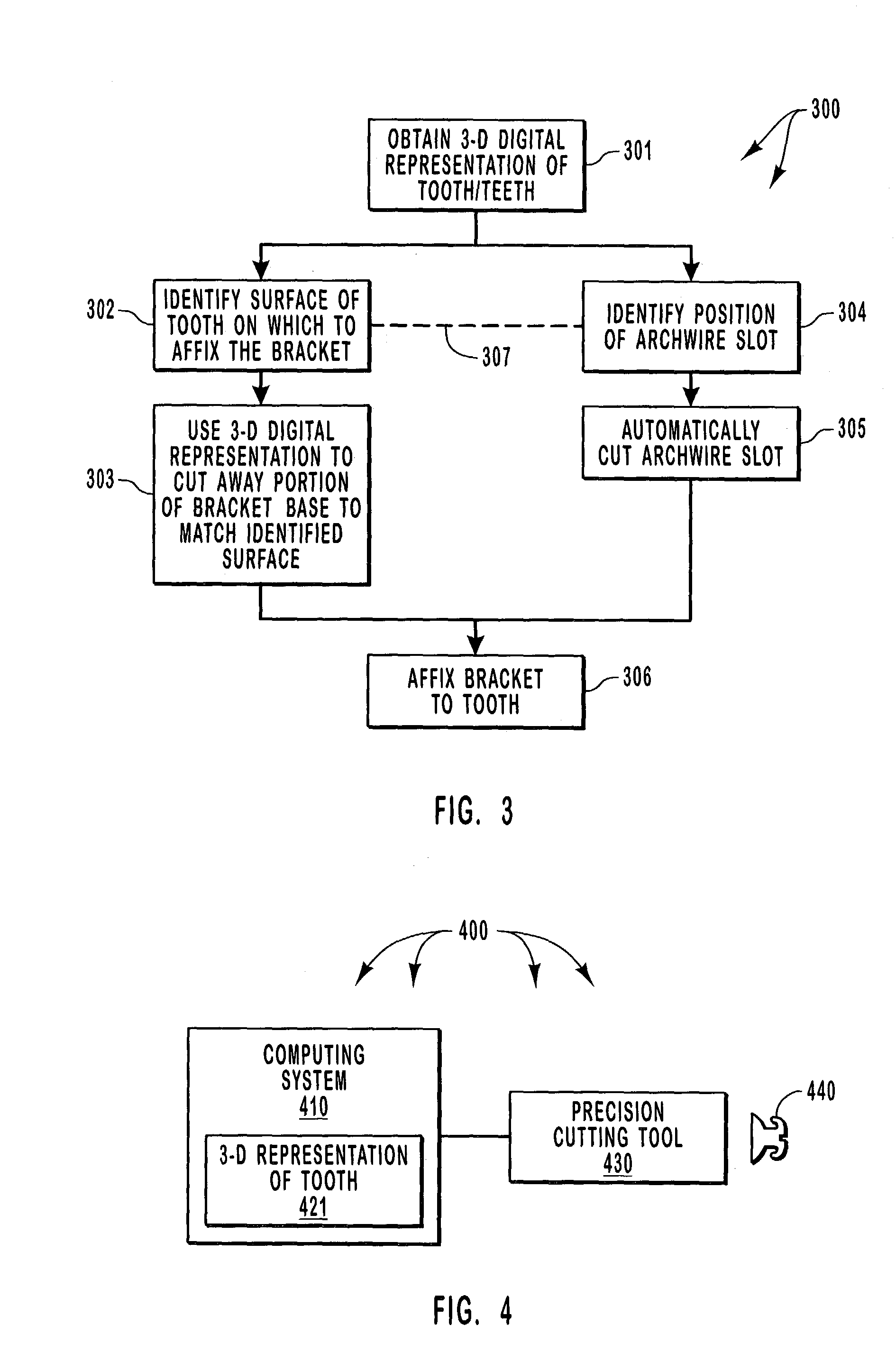
[0029]The principles of the present invention involve the formation of custom-fitted brackets through the precision removal of material from a pre-manufactured bracket. Material may be removed from the base portion in order to custom-fit the bracket to the appropriate position of the tooth, and / or may be removed from the archwire portion of the bracket in order to allow for customized archwire slot orientation. The determination of what material to remove may be accomplished by acquiring a three-dimensional representation of the teeth, then identifying where the brackets should be ideally placed on the teeth and / or how the archwire should be oriented on each bracket.

[0030]Embodiments within the scope of the present invention include computer-readable media for carrying or having computer-executable instructions or data structures stored thereon. Such computer-readable media can be any available media which can be accessed by a general purpose or special purpose computer. By way of e...


PUM


Abstract

Manufacture of custom brackets in which a three-dimensional representation of the teeth is used to remove portions or the base to custom-bit the tooth to a predetermined tooth surface, and / or to remove portions of the bracket to create an archwire slot in order to provide a custom orientation and position of the archwire slot in the bracket. The ideal tooth surface for bracket placement and / or the ideal archwire orientation at that bracket may be determined in a computerized fashion by forming a three-dimensional representation of a ideal corrected position of the teeth, and then determining where the bracket and archwire would need to be placed on each of the misaligned teeth in order to achieve the ideal correction.

Description

BACKGROUND OF THE INVENTION[0001]1. The Field of the Invention[0002]The present invention relates to orthodontics, and more specifically, to a custom-fitted orthodontic bracket and associated methods and computer program products for manufacturing the orthodontic bracket.[0003]2. Background and Related Art[0004]An individual's jaw, gums and teeth (also referred to herein as an “orthodontic structure”) combine to provide a critical function by allowing the individual to mechanically break down food for safer swallowing and more efficient digestion. Sever malformations or mechanical flaws of the individual's orthodontic structure may also interfere (even if only slightly) with the proper articulation of language. The abilities to properly eat and speak fluidly are essential needs of mankind. Any degradation in these abilities may have a significant impact on the affected individual's quality of living.[0005]Also, human beings have varying concerns about their own appearance and how th...

Claims


Application Information

Patent Timeline
Patent Type & Authority Patents(United States)
IPC IPC(8): A61C3/00A61C7/00A61C7/14A61C13/00
CPCA61C7/00A61C7/146A61C7/14A61C7/002A61C13/0018A61C13/0004
Inventor ABELS, NORBERTBACKES, CLAUS H.
Owner ABELS NORBERT
Why Eureka
Try Eureka