Laryngoscope blade

a technology of laryngoscope and blade, which is applied in the field of laryngoscope, can solve the problems of cross-contamination between patients and infection of medical staff handling equipment, and achieve the effect of avoiding infection and avoiding cross-contamination

Active Publication Date: 2010-11-02
CRANTON GEORGE D +1
View PDF14 Cites 29 Cited by
  • Summary
  • Abstract
  • Description
  • Claims
  • Application Information

AI Technical Summary

Benefits of technology

[0016]An object of the present invention is to provide a laryngoscope of design that utilizes blades whose configuration makes it

Problems solved by technology

Fears have been raised concerning both the possibility of cross-contaminatio

Method used


Image

  • Laryngoscope blade
  • Laryngoscope blade
  • Laryngoscope blade

Examples


Embodiment Construction

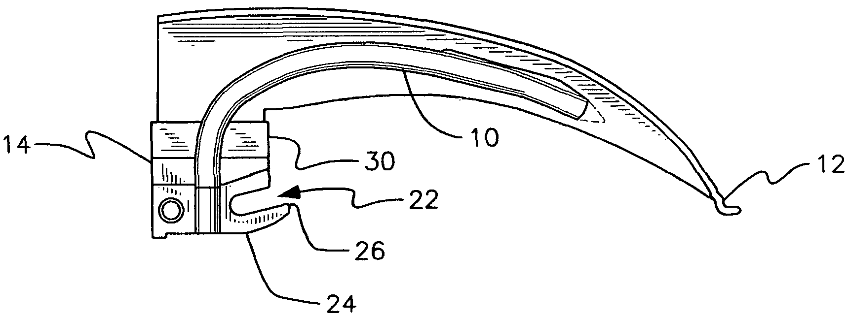
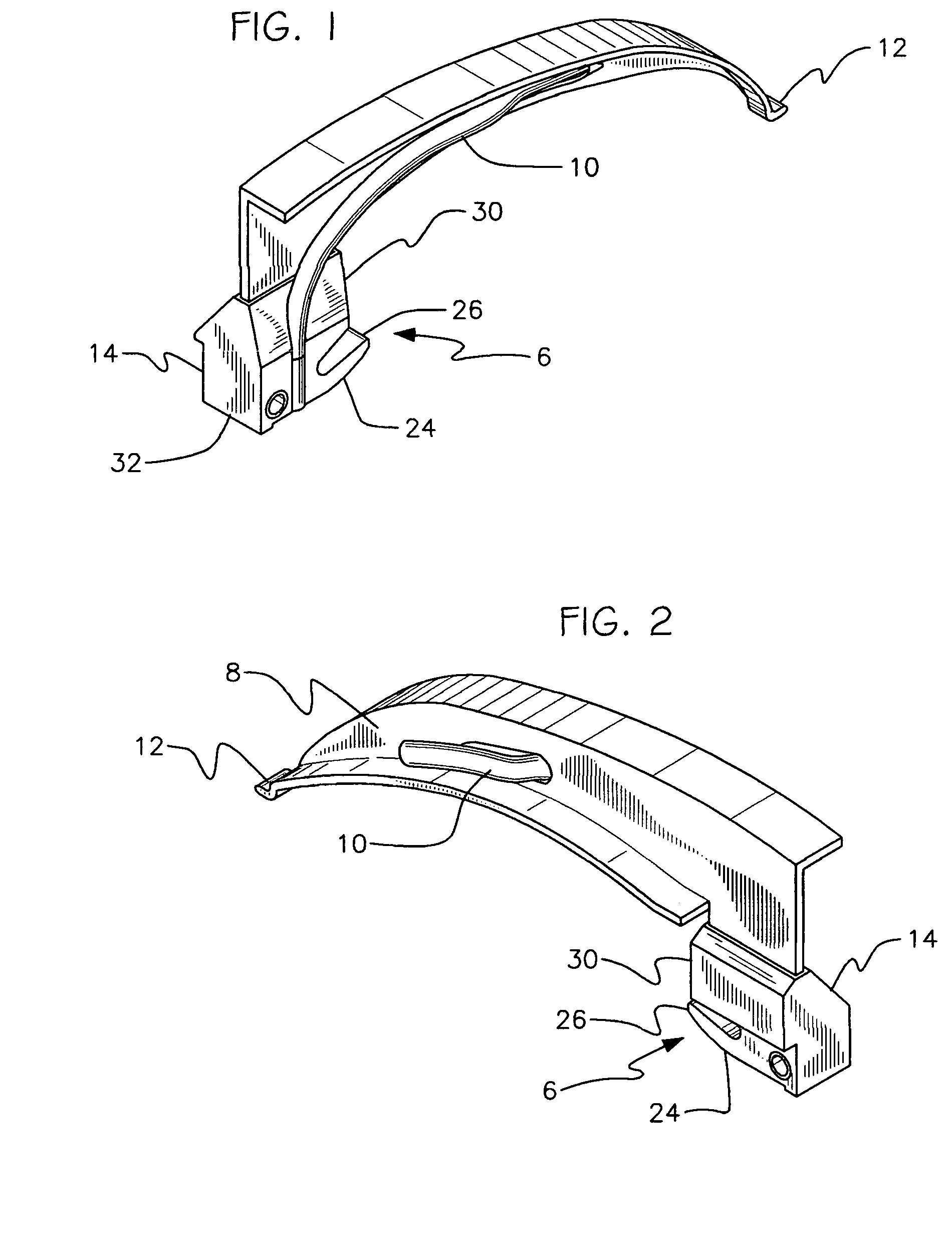
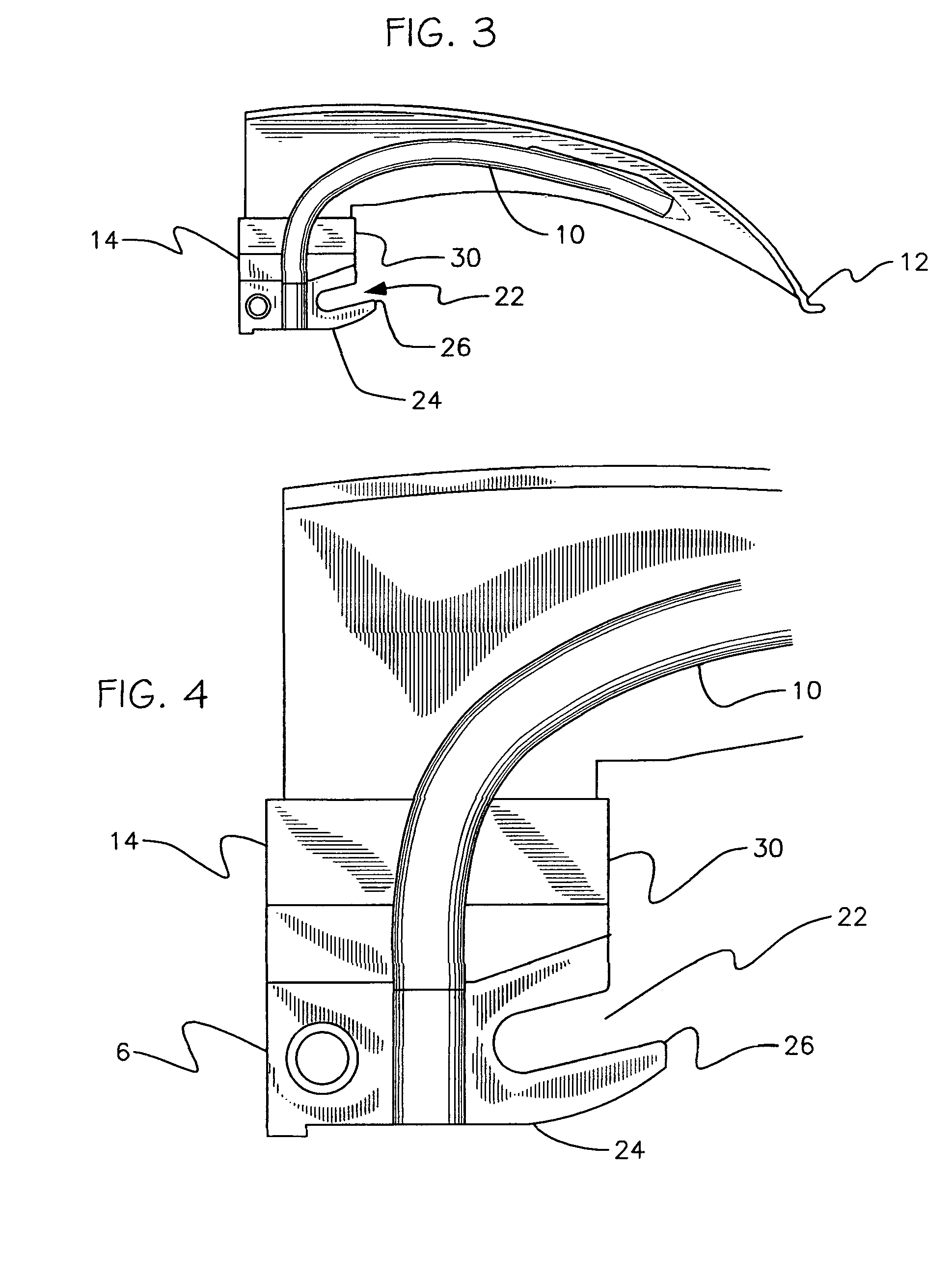
[0042]Referring now to the drawings wherein like numerals are used to reference the same components therein FIG. 7, discloses a laryngoscope blade 4 according to the present invention as used with handle 2 of a laryngoscope. Blade 4 extends substantially at right angles to handle 2. Blade 4 is detachably secured to handle 2 by claw-type fitting 6 and is formed to define a longitudinal right-angled channel 8 to enable a practitioner to see along the length of the blade and thus into a patient's larynx and also to provide a passage for intubation. Blade 4 carries tube 10 of optical fibers in the longitudinal right angle channel 8 for transmitting light from laryngoscope handle 2 toward distal end 12 of blade 4.

[0043]It should be clearly understood that the particular form of laryngoscope blade illustrated in the drawings is only one example of a considerable number of different shaped blades which are commonly available for use in various different circumstances, and that the present ...


PUM


Abstract

A laryngoscope blade is detachably connectable to a hook-on-type laryngoscope handle in conformity with International Standard ISO-7376-1 or ISO 7376-3. The blade comprises a rigid housing having a lower, tongue-engaging flange section extending along the length thereof, a proximal base end provided with hooks or fittings for engaging complementary handle hooks or fittings in compliance with ISO-7376-1 and ISO-7376-3, the proximal base being provided with a hook or flange of such length that the hook or flange comes into contact with the top of the handle such that the blade is prevented from rotating downwardly to such a degree that the distal end of the blade comes into contact with the side of the handle and enabling the blade to be elevated into an operating position to maintain conductivity for powering a light source for the blade.

Description

FIELD OF THE INVENTION[0001]This invention relates to laryngoscopes and particularly to an improved blade for connection to the handle of a laryngoscope to avoid contamination of the handle of the laryngoscope.DESCRIPTION OF THE PRIOR ART[0002]Laryngoscopes generally comprise a blade and a cooperating handle which are connected together in a generally L-shaped configuration. The handle normally serves as an enclosure for one or more batteries which energize a light source which will illuminate the blade. The means for activating the light source is operated by the blade when it is connected to the handle and placed into the operating or usable position. In fiber optics, the light from the bulb passes through a clear light conductor to the distal end of the blade to illuminate the patient's mouth and larynx during the examination thereof by medical personnel where in a conventional laryngoscope, the lamp in the blade is actuated. The surface on the blade adjacent to the handle is use...

Claims


Application Information

Patent Timeline
IPC IPC(8): A61B1/267
CPCA61B1/0008A61B1/00105A61B1/0676A61B1/0684A61B1/267
Inventor CRANTON, GEORGE D.WALL, BARRY L.
Owner CRANTON GEORGE D
Why Eureka
Try Eureka