Antenna with active elements

a technology of active elements and antennas, applied in the field of wireless communication, can solve the problems of not being easily excited at such low frequencies, and it is difficult to design internal antennas for varying frequency applications to accommodate the small form factors

Active Publication Date: 2010-11-09
KYOCERA AVX COMPONENTS (SAN DIEGO) INC
View PDF7 Cites 153 Cited by
  • Summary
  • Abstract
  • Description
  • Claims
  • Application Information

AI Technical Summary

Problems solved by technology

In addition, the design of low frequency dual band internal antennas for use in modern cell phones poses other challenges.
One problem with existing mobile device antenna designs is that they are not easily excited at such low frequencies in order to receive all broadcasted signals.
In particular, with present cell phone, PDA, and similar communication device designs leading to smaller and smaller form factors, it becomes more difficult to design internal antennas for varying frequency applications to accommodate the small form factors.

Method used


Image

  • Antenna with active elements
  • Antenna with active elements
  • Antenna with active elements

Examples


Embodiment Construction

[0028]In the following description, for purposes of explanation and not limitation, details and descriptions are set forth in order to provide a thorough understanding of the present invention. However, it will be apparent to those skilled in the art that the present invention may be practiced in other embodiments that depart from these details and descriptions.

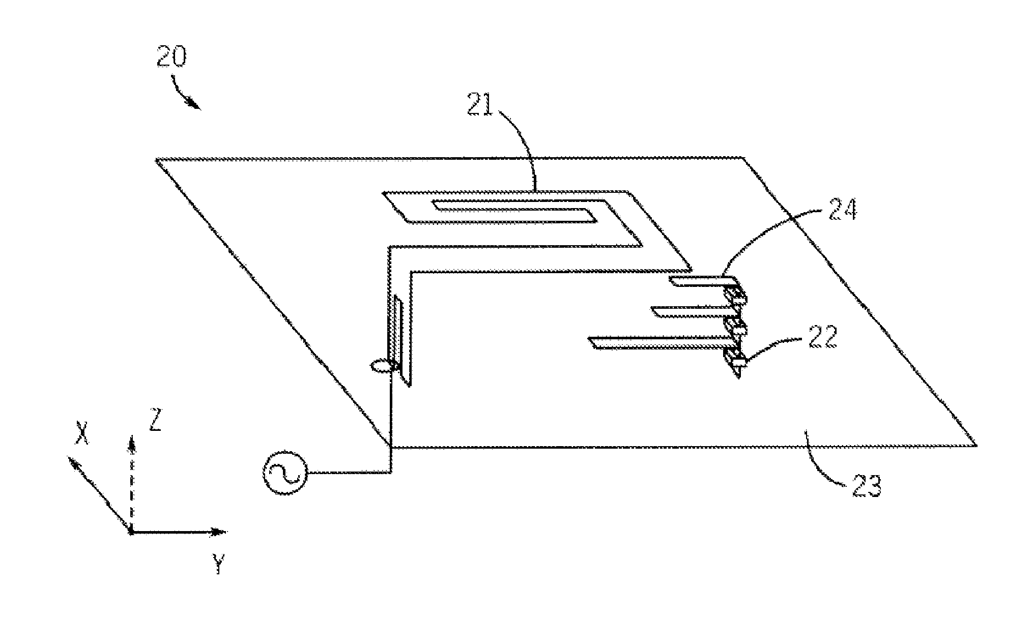
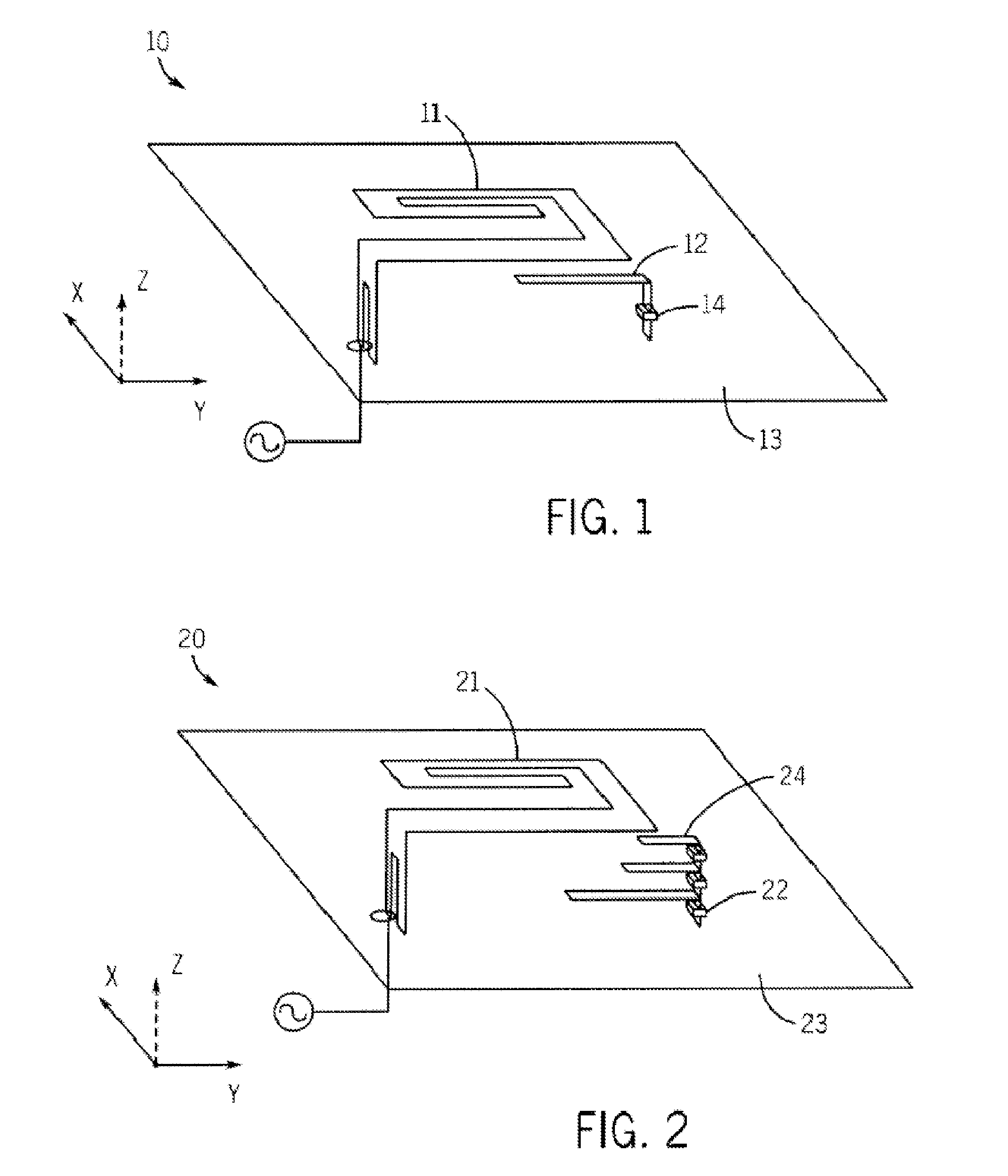
[0029]Referring to FIG. 1, an antenna 10 in accordance with an embodiment of the present invention includes an Isolated Magnetic Dipole (IMD) element 11 and a parasitic element 12 with an active tuning element 14 situated on a ground plane 13 of a substrate. In this embodiment, the active tuning element 14 is located on the parasitic element 12 or on a vertical connection thereof. The active tuning element can be any one or more of voltage controlled tunable capacitors, voltage controlled tunable phase shifters, FET's, switches, MEMs device, transistor, or circuit capable of exhibiting ON-OFF and / or actively controllable cond...


PUM

PropertyMeasurementUnit
frequency responseaaaaaaaaaa
frequencyaaaaaaaaaa
lengthaaaaaaaaaa

Abstract

A multi-frequency antenna comprising an IMD element, active tuning elements and parasitic elements. The IMD element is used in combination with the active tuning and parasitic elements for enabling a variable frequency at which the antenna operates, wherein, when excited, the parasitic elements may couple with the IMD element to change an operating characteristic of the IMD element.

Description

FIELD OF INVENTION[0001]The present invention relates generally to the field of wireless communication. In particular, the present invention relates to an antenna for use within such wireless communication.BACKGROUND OF THE INVENTION[0002]As new generations of handsets and other wireless communication devices become smaller and embedded with more and more applications, new antenna designs are required to address inherent limitations of these devices. With classical antenna structures, a certain physical volume is required to produce a resonant antenna structure at a particular radio frequency and with a particular bandwidth. In multi-band applications, more than one such resonant antenna structure may be required. With the advent of a new generation of wireless devices, such classical antenna structure will need to take into account beam switching, beam steering, space or polarization antenna diversity, impedance matching, frequency switching, mode switching, etc., in order to reduc...

Claims


Application Information

Patent Timeline
Patent Type & Authority Patents(United States)
IPC IPC(8): H01Q9/16H01Q1/24H01Q5/321H01Q5/371H01Q5/385H01Q5/392
CPCH01Q1/243H01Q9/0442H01Q9/145H01Q5/392H01Q5/371H01Q5/385H01Q9/42Y10T29/49016H01Q5/321
Inventor SHAMBLIN, JEFFHAN, CHULMINJONES, ROWLANDROWSON, SEBASTIANDESCLOS, LAURENT
Owner KYOCERA AVX COMPONENTS (SAN DIEGO) INC
Why Eureka
Try Eureka